

The Gulf Cooperation Council (GCC) region is synonymous with monumental industrial achievements. From colossal desalination plants and petrochemical refineries to the world’s largest district cooling networks, these facilities form the backbone of the Middle East’s economy. Powering these heavy operations requires immense rotating machinery. To safely integrate this equipment, partnering with an expert electrical engineering consulting in Dubai firm is absolutely critical within the initial design phase. Starting the massive motors required for these heavy industrial processes places extreme, violent stress on the electrical network.
When a multi-megawatt compressor or a high-capacity chilled water pump is energized, it does not draw power smoothly; it demands a massive, instantaneous surge of electricity from the grid. In a tightly integrated industrial electrical plant, this sudden demand can act like a localized black hole, pulling down the voltage of the entire facility and threatening the stability of the public utility grid.
To prevent catastrophic electrical failures, project developers, EPC contractors, and facility managers must conduct rigorous motor starting study GCC protocols before a single piece of equipment is purchased. These studies are the ultimate diagnostic tool, simulating the intense milliseconds of a motor start to ensure the facility’s electrical backbone can withstand the shock. This comprehensive guide explores the physics of motor inrush currents, mitigation strategies, DEWA/SEC compliance, and how these critical studies shape the procurement and design of GCC industrial plants.
The Physics of Motor Inrush Current
To understand why a motor starting study is essential, one must first look at the inherent physical properties of the industrial workhorse: the AC induction motor.
The Magnetic Deficit at Standstill
When an induction motor is at rest, there is no rotating magnetic field, and the rotor is physically stationary. When voltage is applied across the stator terminals, the motor acts almost exactly like a transformer with a short-circuited secondary winding.
- The Inrush: To magnetize the air gap and overcome the immense physical inertia of the attached mechanical load (like a massive water pump impeller), the motor demands an astronomical amount of power. This is known as the motor inrush current.
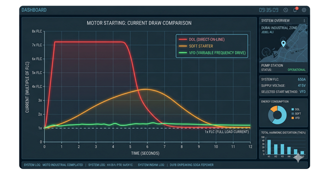
- The Multiplier: During a standard induction motor startup, the motor will typically draw between 5 to 8 times its normal Full Load Current (FLC). For example, a 2,000 kW (11kV) motor with a running current of 130 Amps will suddenly attempt to draw over 800 Amps the moment it is switched on.
The Electrical Shockwave
This massive current flows through the utility cables, transformers, and switchboards. Because every electrical component has inherent impedance (resistance), pushing 800 Amps through the system creates a massive voltage drop ($V = I \times Z$). The larger the motor relative to the power supply, the deeper and more destructive this voltage drop becomes.
System Voltage Dip and Its Consequences
The primary objective of a motor starting study is to calculate the severity of this voltage drop and prevent the disastrous domino effect it can trigger across the industrial facility.
The Domino Effect
If a massive motor causes the system voltage dip to fall below 80% or 85% of nominal voltage, chaos ensues in an industrial plant:
- Contactor Dropout: The magnetic coils holding the circuit breakers and contactors closed for other running motors will lose their magnetic grip, causing running machinery to trip offline indiscriminately.
- Electronic Reboot: Sensitive Programmable Logic Controllers (PLCs), SCADA networks, and variable speed drives will detect the undervoltage, reboot, or shut down to protect themselves, completely halting the manufacturing process.
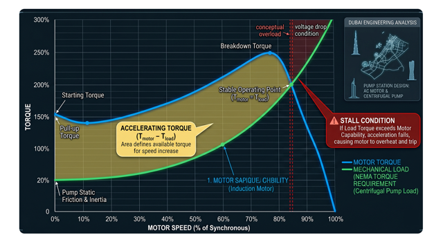
- Motor Stalling: The torque produced by an induction motor is proportional to the square of the voltage. If the voltage drops by 20%, the motor’s starting torque drops by 36%. If the torque drops below what is required to turn the mechanical load, the motor will stall, drawing locked-rotor current until it burns out or the breaker trips.
Utility Grid Compliance
Beyond internal plant issues, pulling down the voltage affects neighboring facilities. Regional utility providers heavily regulate this. DEWA voltage flicker limit and SEC grid codes strictly dictate the maximum allowable voltage dip at the Point of Common Coupling (PCC). If your facility’s motor starting event causes a voltage dip exceeding utility thresholds (often strictly capped at 3% to 5% for frequent starts), DEWA will refuse to energize the plant until mitigation strategies are proven.
Direct-on-Line (DOL) vs. Soft Starters vs. VFDs
When the motor starting study reveals that the inrush current will crash the voltage, the electrical design must be altered. Engineers have three primary weapons to combat massive starting currents.
1. Direct-on-Line (DOL)
- The Method: Connecting the motor directly to the full utility voltage.
- The Reality: DOL motor starting provides the absolute highest starting torque but draws the absolute highest current. It is incredibly cheap but brutal on the electrical grid and the mechanical couplings. In modern GCC heavy industry, DOL is rarely acceptable for motors over a few hundred kilowatts unless the facility has a massive, highly stiff dedicated utility substation.
2. Solid-State Soft Starters
- The Method: Using power electronics (thyristors) to gradually ramp up the voltage applied to the motor over a set time (e.g., 10 to 20 seconds).
- The Reality: This successfully limits the starting current to 3x or 4x FLC, protecting the grid. However, because torque drops with the square of the voltage, a soft starter drastically reduces starting torque. If connected to a “high inertia” load like a loaded conveyor belt or a heavy crusher, the motor may not have enough torque to move the machine at all.
3. Variable Frequency Drives (VFD)
- The Method: The VFD converts AC to DC, and then back to AC, allowing the drive to precisely control both the voltage and the frequency applied to the motor.
- The Reality: A VFD is the ultimate solution. It can deliver 100% full-load torque at zero speed while drawing almost no inrush current (typically staying below 1.5x FLC). The VFD vs soft starter debate often ends here for massive loads.
Expert electrical plant engineering uae evaluates the cost, physical footprint, mechanical load requirements, and grid impact to select the exact right starting method for each drive, balancing CAPEX against operational stability.
Generator Sizing for Black Starts
One of the most complex, high-risk scenarios in GCC industrial design is starting a massive motor when the main DEWA/SEC grid is down, using only the emergency diesel generators.
The “Black Start” Challenge
When a refinery loses power, essential loads, like massive fire water pumps or emergency cooling chillers, must start immediately.
- The Reactive Power Surge: Generators are relatively small, “weak” power sources compared to the municipal grid. The massive reactive power (kVAR) demanded during a motor start will severely drag down the voltage output of the generator’s alternator.
- Generator Sizing: This is why generator sizing for motor start requires specialized engineering. You cannot size a black start generator based on the motor’s running kilowatts (kW). The generator’s alternator must be heavily oversized specifically to handle the transient starting kVA (skVA) of the largest motor stepping onto the bus, ensuring the alternator’s subtransient reactance ($X”d$) does not cause the voltage to collapse and stall the generator engine.
Static vs. Dynamic Motor Starting Studies
The methodology used to analyze the starting event dictates the accuracy and safety of the final design. Engineers employ two different tiers of study.
Static Motor Starting Analysis
A static study is essentially a complex, instantaneous snapshot. It calculates the voltage drop at “Time = 0,” assuming the motor is drawing its absolute maximum locked-rotor current. It is mathematically simpler and generally acceptable for smaller motors where the start time is less than two seconds, providing a conservative “worst-case” voltage dip value.
Dynamic Motor Starting Analysis
For heavy industrial loads, such as massive district cooling centrifugal chillers or high-inertia fans, a static study is dangerously insufficient. Engineers must execute a dynamic motor starting analysis.
- The Simulation: This study utilizes advanced software (like ETAP) to simulate the entire starting sequence over time. It models the motor’s specific speed torque curve modeling against the mechanical load’s counter-torque curve.
- Load Inertia: It calculates exactly how long the motor will take to reach full speed (e.g., 15 seconds) based on the combined inertia ($WK^2$) of the motor and the machine it is driving. If the voltage drops during the start, the software dynamically recalculates the reduced motor torque to verify if the motor will successfully accelerate or if it will stall mid-start. For multi-megawatt MV motors, local GCC utilities and consultants legally mandate dynamic studies.
Impact on Transformer and Cable Sizing
The sheer brutality of a heavy motor start forces electrical engineers to completely rethink how they size the passive infrastructure that feeds the motor.
The Thermal Stress on Cables
A standard electrical cable is sized based on its ability to dissipate the heat generated by its continuous running current. However, if a massive fan motor takes 25 seconds to reach full speed, the cable will be subjected to 600% of its rated current for almost half a minute.
- Cable Withstand: This creates extreme thermal stress ($I^2t$ heating). A comprehensive motor starting study dictates the cable thermal withstand requirements, frequently forcing engineers to upsize the cables by one or two cross-sectional area sizes simply to survive the startup heat, even if the running current doesn’t mathematically require it.
Transformer Sizing and CAPEX
Similarly, transformer sizing motor start considerations are critical. A 2,000 kVA transformer might easily handle the running load of a facility, but if a 1,500 kW motor attempts a DOL start, the transformer’s internal impedance will cause a severe voltage crash on its secondary side. Engineers must strike a delicate balance: sizing the transformer large enough to provide a “stiff” source that minimizes voltage dip, without needlessly ballooning the project’s Capital Expenditure (CAPEX) with grossly oversized, underutilized transformers.
Integration with Protection Coordination
A motor starting event looks, electronically, exactly like a severe short-circuit fault to the building’s protection relays. Designing a system that can tell the difference is a critical engineering art.
The Protection Paradox
The fundamental challenge of motor protection coordination is ensuring the circuit breaker does not trip during the massive 600% starting current, but still trips instantly if a genuine short circuit occurs a fraction of a second later.
- Relay Settings: Engineers must carefully design the overcurrent relay setting (ANSI Codes 50/51) to create a custom “trip curve.” This mathematical curve must be shaped to sit safely above the dynamic motor starting curve (allowing the motor to start without nuisance tripping), but safely below the motor’s thermal damage curve (ensuring the breaker trips before the motor windings melt if the motor stalls).
- Thermal Overload: Furthermore, advanced relays (ANSI Code 49) are programmed using the data from the dynamic study to track the thermal capacity of the motor, preventing operators from attempting too many successive starts that would bake the motor’s insulation.
Procurement Strategy for Heavy Drives
The results of a motor starting study are not just technical reports; they are the primary driver of the project’s procurement timeline.
The Long-Lead Reality
If a preliminary static study assumed a motor could be started DOL, but a later dynamic study proves that a VFD is mandatory to prevent utility voltage collapse, the project is in severe danger.
- Supply Chain Bottlenecks: Massive, customized medium-voltage VFDs or heavy-duty soft starters are not kept in warehouses. Medium voltage VFD procurement involves highly customized manufacturing, testing, and shipping logistics that can take 8 to 14 months.
- Strategic Sourcing: Executing the motor study during the earliest concept phases directly feeds into precise Electrical Plant Procurement. It locks in the technical specifications for these critical-path, long-lead items. By identifying the exact starting methodology early, project managers secure their industrial electrical sourcing pipeline, preventing catastrophic, last-minute multi-million-dirham specification changes that derail the facility’s construction schedule.
Frequently Asked Questions (FAQ)
1. What is the standard DEWA voltage dip limit for motor starting?
While it depends on the stiffness of the local grid connection, DEWA generally limits the allowable voltage dip at the Point of Common Coupling (PCC) to 3% for frequent motor starts, and up to 5% for infrequent starts. If your study shows a higher dip, you will be required to change your starting method (e.g., from DOL to a VFD) before connecting to the grid.
2. Can I use a Star-Delta starter for a heavy industrial compressor?
Star-Delta starters reduce the starting current to about 33% of a DOL start, which helps the electrical grid. However, they also reduce the starting torque to 33%. For a heavy, high-inertia load like a massive industrial compressor or a fully loaded conveyor belt, 33% torque is usually not enough to turn the machine, causing the motor to stall and burn out. They are better suited for low-inertia loads like unloaded centrifugal fans.
3. Why does starting a motor on a diesel generator cause the lights to flicker?
A diesel generator has a relatively high internal impedance (specifically, subtransient reactance) compared to the massive municipal utility grid. When a motor pulls a sudden 600% inrush current, the generator’s alternator struggles to maintain the magnetic field, causing a sharp, immediate voltage drop across the generator’s output busbar, which visually manifests as flickering lights or tripping equipment.
4. What is a “Locked Rotor” current?
When you first apply voltage to a motor, the rotor is physically locked at 0 RPM due to its own mass. In this exact fraction of a second, the motor draws its absolute maximum possible current from the grid. This is the “Locked Rotor Current,” and it is the peak value used by engineers to calculate the worst-case voltage dip during a static motor starting study.
5. How does a VFD prevent voltage dips during motor starting?
A Variable Frequency Drive (VFD) converts the incoming AC power to DC, and then electronically builds a new AC wave to feed the motor. By starting the motor at a very low frequency (e.g., 2Hz) and low voltage, and slowly ramping them both up together, the VFD allows the motor to produce 100% of its full-load torque without ever drawing more than 100% to 150% of its running current from the grid, entirely eliminating the massive inrush shockwave.
Conclusion & Next Steps: Powering Up Safely
In the heavy industrial landscape of the GCC, the moment a massive motor is energized is the ultimate stress test of the facility’s electrical design. A motor starting study is the critical firewall protecting an industrial plant’s operational stability from the violent physics of induction machinery.
Relying on generic assumptions, outdated rules of thumb, or neglecting to perform a dynamic analysis on high-inertia loads is a recipe for disaster. It leads to stalled production lines, melted cables, utility grid penalties, and catastrophic equipment failures that cost millions of dirhams in unrecoverable downtime. By integrating rigorous motor studies early in the design cycle, developers ensure that their heavy infrastructure powers up smoothly, safely, and in absolute compliance with stringent regional grid codes.
Are you designing a facility with massive rotating equipment?
Do not leave the stability of your power network to chance. Navigating the complex interplay of dynamic load inertia, voltage drop, and advanced VFD integration requires profound analytical expertise. Partner with our specialized industrial motor study consultant team to ensure flawless motor integration. At Elecwatts, we provide the cutting-edge dynamic modeling and GCC electrical engineering oversight required to guarantee your heavy industrial plant operates seamlessly under the most extreme conditions.
Contact Elecwatts today to secure the dynamic stability and operational future of your industrial facility.