When a major underground power cable fails in an industrial plant or a sprawling residential district in the Gulf Cooperation Council (GCC), the clock starts ticking immediately. Operations and Maintenance (O&M) teams face immense, high-stakes pressure. Every minute of power loss translates to escalating financial penalties, halted production lines, or compromised essential services. In these critical moments, relying on top-tier electrical engineering consulting in Dubai expertise to guide fault isolation is a game-changer. The ultimate objective is to execute rapid, non-destructive fault location to bring the facility back online as quickly as possible.
Historically, finding a broken cable meant days of blind excavation, destroying landscaping and concrete in a desperate search for the break. Today, modern cable fault location GCC protocols rely on highly sophisticated acoustic and electromagnetic technologies. However, deploying these tools successfully requires a deep understanding of electrical physics and the specific environmental challenges of the region. Mastering underground cable fault finding is an essential skillset for any O&M team tasked with ensuring the reliability of the Middle East’s vast, buried electrical infrastructure.
The Impact of Desert Terrain on Fault Location
Locating a cable fault in the GCC is fundamentally more difficult than in temperate, damp climates like Europe or North America. The physical environment actively works against the technician.
The primary obstacle in desert cable fault location is the soil itself. Dry, aerated desert sand and rocky limestone are excellent acoustic insulators. When a fault is forced to “spark” underground, the resulting sound waves are heavily muffled by the dry earth, making them incredibly difficult to hear at the surface.
Furthermore, GCC underground electrical maintenance is complicated by the depth of installation. To avoid the intense surface heat and protect against mechanical damage, critical high-voltage cables in the Gulf are often buried much deeper (up to 1.5 meters or more) than in other regions. When you combine deep burial, sound-deadening sandy soil, and the high ambient noise of heavy industrial zones or bustling cities like Dubai or Riyadh, traditional acoustic pinpointing becomes a monumental challenge, demanding advanced, specialized equipment.
Step 1: Cable Isolation and Insulation Resistance Testing
Before any complex electronic “radar” is connected to a cable, the fundamental nature of the fault must be established. The first and most critical step is human and equipment safety: the affected cable must be strictly isolated, locked out, and tagged out (LOTO) at both ends.
Once safe, technicians execute insulation resistance testing. Using a high-voltage Megohmmeter (often colloquially called a cable megger test), the O&M engineer injects a DC voltage between the phase conductors and the earth screen. This test does not find the location of the fault, but it diagnoses its “personality.”
- Short Circuit: A phase-to-phase fault with zero resistance.
- Open Circuit: A severed cable with infinite resistance.
- Earth Fault: A phase shorting to the metallic cable sheath or the ground.
Understanding this resistance value dictates exactly which advanced fault location method must be deployed next.
Step 2: Pre-Location with Time Domain Reflectometry (TDR)
For low-resistance faults or open circuits, the fastest and most effective tool is a Time Domain Reflectometer (TDR).
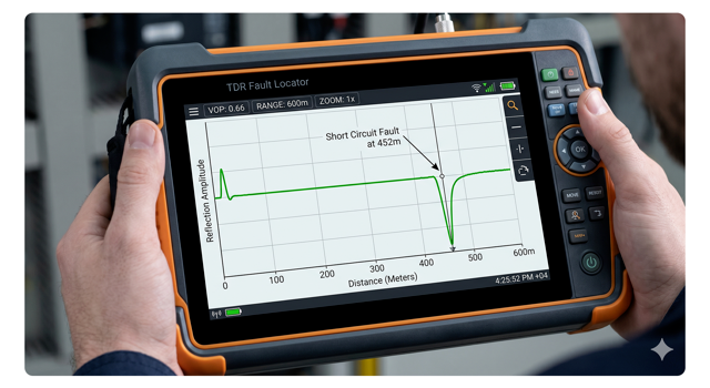
TDR cable fault location operates identically to radar. The device injects a low-voltage, high-frequency electrical pulse down the copper or aluminum core of the isolated cable. When this pulse encounters a change in impedance, such as a severed cable end, a splice joint, or a hard short circuit, a portion of the signal reflects back to the TDR device.
Because the speed at which the pulse travels through a specific type of cable is a known constant (the Velocity of Propagation), the TDR simply measures the time it takes for the echo to return. It instantly calculates the distance, telling the technician that the fault is, for example, exactly 452 meters down the line. However, time domain reflectometry electrical diagnostics have a major limitation: a low-voltage TDR pulse will pass straight through a “high-resistance” fault (a pinhole burn in the insulation) without reflecting, rendering the fault invisible to standard TDR.
High-Resistance Faults and the Surge Generator (Thumper)
When the Megger test indicates a high-resistance fault, the low-voltage TDR is useless. The fault is essentially acting like a tiny, highly resistive resistor that needs to be broken down. This requires brute force.
The standard tool for this is the surge wave generator, widely known in the industry as a “Thumper.” The cable thumping method involves charging a massive internal capacitor and releasing a high-voltage, high-energy DC surge (often 16kV to 32kV) directly into the faulted cable.
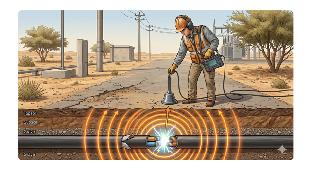
When this massive surge reaches the microscopic pinhole fault, it forces the electricity to jump the gap. This creates a powerful, localized electrical arc, a miniature lightning strike underground. This arc generates a loud, physical “thump” (an acoustic wave) and an electromagnetic pulse. The thumper fires repeatedly every few seconds, giving the technicians a repeating signal to track on the surface.
Arc Reflection Method (ARM): The Best of Both Worlds
While thumping is highly effective, repeatedly blasting a cable with 32kV surges is highly destructive. It can weaken the healthy insulation in other parts of the cable, creating new faults that will fail in the future. Modern engineering has solved this with the arc reflection method (ARM).
ARM is the pinnacle of advanced cable diagnostics. It seamlessly combines the high-voltage Surge Generator with the low-voltage TDR.
- How it Works: The thumper sends a single high-voltage surge to create an arc at the fault site. For a few milliseconds, that arc temporarily turns the high-resistance fault into a low-resistance short circuit. In that exact millisecond, the TDR fires its low-voltage pulse. The TDR pulse hits the temporary arc and reflects back perfectly.
This gives the technician the exact distance to the fault using only one or two thumps, drastically reducing the electrical stress applied to the aging cable network.
Step 3: Pinpointing with Acoustic and Magnetic Receivers
The ARM or TDR provides the “pre-location” (e.g., the fault is 452 meters away). The technician then measures 452 meters along the ground. However, cable routes are rarely perfectly straight. The final step is exact “pinpointing” before bringing in the heavy excavators.
Technicians walk the suspected area using highly sensitive acoustic cable pinpointing equipment, essentially a highly advanced electronic stethoscope placed on the ground. The thumper is set to fire at a low repetition rate. The technician listens for the loudest “thump” underground, pinpointing the exact square meter to dig.
Simultaneously, the equipment utilizes magnetic cable tracing. The underground arc also releases an electromagnetic pulse. By measuring the time delay between the magnetic flash (which travels at the speed of light) and the acoustic thump (which travels at the speed of sound through dirt), the receiver can calculate exactly how deep the fault is buried, ensuring pinpoint accuracy even for unmapped legacy cables.
Sheath Fault Location for HV Cables
For 11kV and 33kV networks, waiting for the main XLPE insulation to fail causes massive outages. A truly resilient O&M strategy involves finding damage before the cable fails. This involves targeting the outer PVC or PE protective sheath.
If a contractor accidentally nicks the outer sheath of a buried cable with a shovel, moisture from the saline GCC soil will slowly seep in, eventually destroying the copper screen and the main insulation.
To find this pinpoint damage, engineers use cable sheath fault location techniques, specifically the step voltage method. A DC voltage is applied to the cable’s metallic screen. Current leaks out of the tiny hole in the sheath into the surrounding soil, creating a voltage gradient on the ground surface. Technicians walk above the cable route with two probes shaped like walking sticks (an “A-Frame”). The sensitive voltmeter measures the voltage difference between the two probes with each step. The voltage reading will spike dramatically as the technician steps directly over the buried sheath damage, allowing for a proactive, localized repair before a catastrophic short circuit ever occurs.
Developing a Proactive O&M Strategy
The transition from a reactive “fix-it-when-it-breaks” mentality to a proactive cable maintenance strategy is the hallmark of a world-class facility.
The foundation for this strategy is actually laid before the facility even opens. Rigorous Electrical Project Management during the initial construction and commissioning phase is crucial. By mandating comprehensive Very Low Frequency (VLF) testing and Partial Discharge (PD) mapping before the cables are officially energized, project managers establish a pristine “baseline signature” for the entire network.
Years later, O&M teams can perform routine predictive electrical diagnostics, comparing current PD levels against the original commissioning baseline. This allows them to mathematically track the degradation of splices and terminations, predicting exactly which joint will fail and scheduling a surgical repair during a planned maintenance window, entirely eliminating the chaos of an unplanned blackout.
Frequently Asked Questions (FAQ)
1. What is a TDR and how does it work?
TDR stands for Time Domain Reflectometer. It acts like an electrical radar for cables. It sends a low-voltage pulse down the copper wire and measures how long it takes for the pulse’s “echo” to bounce back from a fault or break. Because electricity travels at a known speed, the TDR uses the echo time to calculate the exact distance (in meters) to the problem.
2. Why use a Surge Generator (Thumper)?
A low-voltage TDR pulse will pass straight through a “high-resistance” fault (like a tiny pinhole burn in the insulation) without bouncing back. A Surge Generator or “Thumper” forces a massive burst of high voltage (e.g., 32,000 volts) down the cable. This massive voltage jumps the pinhole gap, creating a loud, physical “thump” underground that technicians can listen for on the surface.
3. What is the Arc Reflection Method (ARM)?
ARM is the most advanced fault location method. Repeatedly “thumping” a cable with 32,000 volts can damage the healthy parts of the cable. ARM solves this by combining the Thumper and the TDR. The Thumper sends one pulse to create a temporary arc at the fault, and the TDR fires simultaneously to bounce its radar pulse off that temporary arc, finding the distance instantly without continuously stressing the cable.
4. How do you find faults on unmapped legacy cables?
Advanced fault location equipment uses magnetic receivers alongside acoustic microphones. When the Thumper creates an arc underground, it emits an electromagnetic pulse. The receiver picks up this magnetic field, allowing the technician to precisely trace the physical path of the unmapped cable under the ground, guiding them exactly to where the acoustic “thump” is loudest.
5. Can sheath faults be located before the cable fails?
Yes, using the “Step Voltage Method.” If the outer plastic jacket of a cable is nicked, voltage is applied to the cable’s metal screen. Current leaks out of the nick into the dirt. A technician uses an A-Frame device with two probes to walk the ground above the cable; the device detects the “voltage gradient” in the dirt, pinpointing the tiny hole in the jacket before moisture destroys the inner insulation.
Conclusion & Next Steps: Minimizing Downtime
In the relentless, 24/7 industrial environment of the GCC, an underground cable fault is a high-stakes emergency. However, it does not need to be a prolonged disaster. The days of blind digging and guessing are over.
By leveraging the precise science of Time Domain Reflectometry, Arc Reflection, and acoustic pinpointing, a skilled O&M team can transform a multi-day excavation nightmare into a surgical, four-hour repair. Equipping your teams with the right advanced diagnostic tools and the engineering knowledge to interpret the data is the ultimate investment in cable reliability engineering.
Need a resilient cable network designed to prevent faults in the first place?
A proactive approach starts with exceptional design and rigorous testing. Leverage our expert engineering and O&M oversight to safeguard your infrastructure. Contact Elecwatts today to elevate your GCC electrical O&M strategy from reactive troubleshooting to predictive excellence.
Contact Elecwatts today to secure the operational uptime of your underground power networks.