

In the execution of multi-megawatt industrial, utility, and commercial developments across the GCC, the final transition from paper plans to physical site execution is a high-risk zone. Before a single cubic meter of concrete is poured or a single kilometer of heavy armored cable is pulled, developers must run their plans through an uncompromising quality assurance firewall. Partnering with an expert electrical consultancy to perform a comprehensive design audit is the most effective way to eliminate costly errors.
A rigorous electrical QA QC design review is not an administrative luxury; it is a financial necessity. The cost of correcting an engineering error scales exponentially as a project progresses. Finding a mathematical discrepancy in a transformer rating during the “Issued for Construction” (IFC) stage costs virtually nothing—it is resolved with a few clicks on a digital model. However, discovering that same error during site commissioning can cost millions of dirhams in scrapped equipment, prolonged legal disputes, and catastrophic project delays. Implementing a robust electrical design review checklist before breaking ground is the ultimate safeguard for your project timeline and budget.
Utility and Regulatory Compliance Checks
The first technical gate of the design audit must verify that the engineering plans align perfectly with local utility and municipal safety regulations. A non-compliant drawing will never receive an energization certificate.
- Check 1: Verify that the correct utility-specific diversity factors have been applied to the overall load calculations in compliance with DEWA electrical regulations, SEC, or KAHRAMAA guidelines.
- Check 2: Confirm that the main incoming circuit breaker rating does not exceed the maximum power allocation permitted by the utility’s No Objection Certificate (NOC).
- Check 3: Ensure that all emergency lighting, exit signs, and central battery systems comply with local Civil Defense (e.g., DCD) emergency autonomy standards (typically requiring 3 hours of continuous backup).
- Check 4: Validate that the dedicated fire pump power supply is routed through a fire-rated path completely separate from the building’s main low-voltage switchboard, ensuring fire containment operations remain active under all conditions during a utility compliance review.
Load Schedule and SLD Verification
The Single Line Diagram (SLD) is the master map of your entire power network. If the SLD is not perfectly coordinated with the individual branch load schedules, the physical installation will suffer immediate protection failures.
- Check 5: Perform a comprehensive SLD verification to ensure that every single cable tag, breaker frame size, and trip setting matches the corresponding data on the active load schedules.
- Check 6: Confirm that the calculated total demand load matches the sizing of the main incoming busbars, incorporating a mandatory minimum $20\%$ spare capacity for future expansion.
- Check 7: Audit the phase balance across all major three-phase distribution boards, verifying that the load imbalance between phases does not exceed the utility-mandated limit (typically $<5\%$) to prevent neutral overheating.
- Check 8: Validate the protection cascading and discrimination settings, ensuring that a localized fault on a minor branch circuit will trip the immediate branch breaker without causing a cascading trip of the main incoming breaker during an electrical load schedule check.
Equipment Sizing and Ratings
Sizing heavy electrical assets requires balancing the physical realities of peak starting currents with long-term thermal capacity.
- Check 9: Execute a rigorous transformer sizing check to prove that the oil or dry-type transformers can safely support the peak facility load plus $20\%$ future growth without exceeding their thermal insulation classes.
- Check 10: Verify that the emergency generator has sufficient generator inrush capacity to start the massive starting currents of the facility’s fire pumps or HVAC chillers without suffering severe voltage dips or engine stalling.
- Check 11: Confirm that the power factor correction (PFC) capacitor banks are equipped with detuned reactors ($7\%$ or $14\%$) to prevent harmonic resonance from destroying the capacitor cells.
- Check 12: Ensure that all outdoor equipment specified for the project (such as package substations and ring main units) is fully rated to operate continuously in ambient desert temperatures of up to $50^\circ\text{C}$ without de-rating.
Cable Sizing and Derating Validation
Cables are the highly expensive arteries of your facility’s power network. Sizing them based on generic catalog values without calculating local environmental penalties is a recipe for physical cable melt-downs.
- Check 13: Confirm that the Cable engineering calculations have applied precise GCC-specific thermal derating factors, accounting for elevated ground temperatures ($35^\circ\text{C}$ to $40^\circ\text{C}$) and high soil thermal resistivity ($1.5$ to $2.5\text{ K}\cdot\text{m/W}$).
- Check 14: Execute a comprehensive cable derating check for grouping, proving that cables bundled together in trenches or on trays have been derated to account for mutual heating.
- Check 15: Conduct a strict voltage drop verification, proving that the voltage drop from the primary utility source to the furthest sub-main panel does not exceed $2.5\%$, and does not exceed $4\%$ for final branch circuits under full load, using the formula:
- $$V_{drop} = \sqrt{3} \times I \times L \times (R\cos\theta + X\sin\theta)$$
- Check 16: Ensure that all high-voltage and medium-voltage cables are specified with continuous, properly sized armor (such as Steel Wire Armor – SWA) to withstand mechanical stresses during burial.
Short Circuit and Protection Coordination
Underestimating the destructive power of a short circuit can lead to catastrophic panel explosions. The switchgear must be engineered to survive the absolute worst-case scenario.
- Check 17: Verify that the rated short-circuit withstand capacity (measured in $kA$ for $1$ or $3$ seconds) of all switchboards is higher than the calculated prospective fault level at that specific busbar.
- Check 18: Confirm that the circuit breaker interrupting capacity ($I_{cu}$) is greater than or equal to the maximum short-circuit current ($I_{sc}$) calculated in the power system analysis and design report.
- Check 19: Conduct a comprehensive protection coordination review to ensure that the time-current curves (TCC) of the protection relays do not overlap, guaranteeing perfect selective tripping.
- Check 20: Verify that the current transformer (CT) ratios and accuracy classes (such as $5\text{P}10$ or $5\text{P}20$) are perfectly matched to the protection relay requirements to prevent CT saturation during a massive short circuit rating check.
Earthing and Lightning Protection Layouts
A robust grounding grid is the ultimate life-safety system, protecting human operators from lethal touch and step voltages.
- Check 21: Perform an earthing design review to ensure the grounding grid configuration matches the host utility’s specific safety philosophy (such as the TN-S mandate in Dubai or the TT system in Qatar).
- Check 22: Verify that the physical earth pit locations are easily accessible for routine testing and are located away from potential mechanical damage or soil-drying heat sources.
- Check 23: Execute a lightning protection checking audit utilizing the rolling sphere method, proving that the protection zone completely shields all rooftop MEP equipment, chiller plants, and solar arrays.
- Check 24: Ensure that the lightning down-conductors are routed along the shortest physical path to the ground pits, avoiding sharp $90^\circ$ bends that can cause dangerous flashovers.
Spatial and MEP Clash Coordination
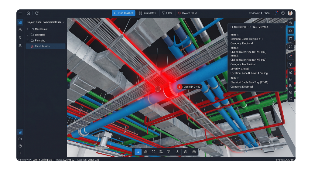
Designing a system on flat, 2D drawings often hides catastrophic physical clashes with other building utilities.
- Check 25: Conduct a comprehensive MEP clash coordination audit, verifying that no wet services (water pipes, drainage, AC condensate lines) are routed directly above or through electrical rooms.
- Check 26: Verify that the physical door swings of the electrical rooms open outwards and are equipped with panic bars, ensuring operators can escape instantly during an arc flash.
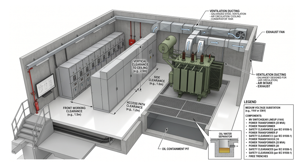
- Check 27: Perform an electrical room clearance check to prove that the physical maintenance zones around all low-voltage panels meet or exceed utility standards (typically $1.5\text{ m}$ of clear space in front of panels).
Bill of Materials (BOM) & Specification Alignment
The final phase of the design review bridges the gap between the drawings and the procurement office, preventing costly material ordering mistakes.
- Check 28: Perform a detailed electrical BOM review to ensure that the physical quantities of components (such as the number of IP65 enclosures or current transformers) on the drawings perfectly match the quantities listed in the procurement schedules.
- Check 29: Execute an equipment specification check to verify that every specified cable brand, circuit breaker model, and transformer manufacturer is listed on the local utility’s Approved Vendor List (AVL).
- Check 30: Ensure that the specifications explicitly mandate that all incoming materials must hold valid SASO certificates (for Saudi Arabia) or local Civil Defense approvals before they are delivered to the construction site.
Frequently Asked Questions (FAQ)
1. What is the difference between an IFC drawing and an As-Built drawing?
An IFC (Issued for Construction) drawing represents the approved, coordinated, and utility-compliant design used by the contractor to physically build the facility on site. An As-Built drawing is created after construction is completed to document any minor, authorized modifications made in the field, representing the exact physical reality of the finished installation.
2. Why is a “wet service” clash in an electrical room a cause for immediate rejection?
Water is highly conductive. If pressurized water pipes, drainage lines, or AC condensation lines are routed directly above or through an electrical room, any minor leak or pipe sweat can drop water onto live $400\text{V}$ busbars or switchgear. This triggers catastrophic short circuits, explosive arc flashes, and total equipment destruction, posing a lethal risk to operators.
3. How does the “rolling sphere method” protect solar arrays?
The rolling sphere method is an advanced lightning protection design technique. Engineers model an imaginary sphere (typically with a $45\text{ m}$ radius) rolling over the 3D model of the building. Any surface that the sphere physically touches is a high-risk zone for a lightning strike. Air terminals (lightning rods) are placed so that they lift the sphere off the delicate solar panels and rooftop MEP equipment, creating a safe “shielding zone.”
4. What is “CT saturation” and why must it be prevented?
Current Transformers (CTs) measure the massive currents flowing through a cable and step them down to a safe, small signal for protection relays to read. During a massive short circuit, the magnetic core of a poorly sized CT can saturate (become magnetically overloaded). When this happens, the CT stops sending accurate current data to the relay, causing the relay to fail to trip the breaker, which can result in the entire switchboard exploding.
5. Why is a 30-point electrical design checklist critical before construction starts?
A 30-point checklist provides a systematic, highly structured QA/QC framework. It ensures that engineering teams do not overlook critical, overlapping variables—such as matching BOM quantities to drawings, verifying local utility diversity factors, auditing cable derating for local soil resistivity, and checking emergency battery capacities—catching costly errors on paper before expensive construction materials are procured and installed.
Systematizing Quality Assurance
Executing a multi-million-dollar development in the GCC requires move beyond basic design assumptions. A rigorous, 30-point electrical design review checklist represents the definitive line of defense between an optimized, highly safe, and utility-compliant installation and a chaotic construction site plagued by constant rejections, design variations, and expensive field rework.
By systematically auditing regulatory compliance, load schedules, equipment sizing, cable derating, short-circuit ratings, and physical spatial coordination on paper, developers and project managers secure their investments and guarantee a seamless path to utility energization.
Need an independent set of expert eyes on your IFC package?
Do not gamble your project budget or construction schedule on uncoordinated drawings. Engage our specialized engineering team to conduct a comprehensive third party electrical review of your plans. As a premier electrical consultancy, Elecwatts delivers the certified technical due diligence, advanced system simulations, and meticulous IFC drawing audit services required to guarantee your project passes every utility inspection on the first attempt.
Contact Elecwatts today to secure the technical and regulatory integrity of your electrical assets.