

In the highly regulated construction environment of the GCC, achieving utility energization requires flawless electrical engineering and design in Dubai. Before a single meter is installed or switchgear energized, utility authorities demand unequivocal proof that your facility is safe, compliant, and built exactly to specification. One of the most common reasons utilities like DEWA (Dubai) and SEC (Saudi Arabia) reject electrical submissions is vague, incomplete, or poorly coordinated cable routing and scheduling documentation.
The cable schedule is far more than a simple list of wires. It serves as the master database that bridges the theoretical calculations of your Single Line Diagram (SLD) with the physical, spatial reality of the construction site. A sloppy DEWA cable schedule submission creates immediate red flags for utility reviewers, leading to weeks of costly delays, revise-and-resubmit cycles, and delayed project handovers. Mastering the precision required for SEC electrical drawing approval is the fastest route to securing your No Objection Certificate (NOC) and getting the power turned on.
Anatomy of a Compliant Cable Schedule
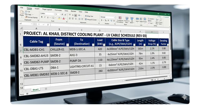
A utility reviewer looks at a cable schedule to verify safety and sizing logic at a glance. To pass this scrutiny, the document must be meticulously organized.
The electrical cable schedule format must include non-negotiable data fields for every single circuit. These fields include:
- Cable Tag/ID: A unique identifier that perfectly matches the drawings.
- Source & Destination: Clearly stating where the power originates (e.g., MDB-Ground) and where it terminates (e.g., SMDB-Floor 2).
- Cable Type: Specifying the exact construction (e.g., Cu/XLPE/SWA/PVC or LSZH).
- Size and Cores: For example, 4C x 240mm² + 1C x 120mm² ECC.
- Estimated Length: Crucial for calculating voltage drops.
Beyond basic identification, comprehensive cable sizing calculation data must be embedded or clearly referenced. This includes showing the specific derating factors applied (ambient temperature, grouping, and burial depth). Grouping this data accurately and logically in an Excel-based format saves utility engineers weeks in the approval process, drastically accelerating your timeline.
Coordination with the Single Line Diagram (SLD)
The most frequent and frustrating reason for submission rejection is a discrepancy between the cable schedule and the SLD.
There is a strict, unforgiving rule in utility submissions: the cable tags, sizes, and protective device ratings on the schedule must perfectly match the submitted SLD. SLD to cable schedule coordination is not optional. When an engineer reviews an application for DEWA SLD approval, they cross-reference these two documents immediately. If the SLD indicates a 185mm² cable feeding a chiller, but the cable schedule lists a 240mm² cable for the same tag, the reviewer instantly assumes the entire design lacks quality control. The entire package will be rejected, forcing the consultant to audit and resubmit the entire design.
2D Routing Drawings: Showing the Physical Reality
While the schedule provides the data, the routing drawings prove that the installation is physically possible within the building’s architecture.
When submitting an electrical routing floor plan, generic lines drawn through walls will not suffice. Utilities expect high-fidelity cable tray layout drawing packages. These drawings must show:
- Exact Tray Widths: Scaled accurately to the architectural floor plan to prove the tray actually fits in the designated corridor.
- Trench Locations: Clearly demarcating underground routes and pull pits.
- Turning Radii: For large High Voltage (HV) or thick Low Voltage (LV) cables, the drawings must visually prove that the physical turning radius of the cable complies with the manufacturer’s limits without crushing the insulation against the tray corners.
Resolving Infrastructure Clashes on Paper
A major concern for utilities and civil defense authorities is spatial conflict. You must prove on paper that your electrical routes are safe and isolated from hazards.
This requires comprehensive MEP clash resolution. The routing drawings must explicitly demonstrate electrical and wet services separation. A cable tray cannot be routed directly beneath a chilled water pipe or a pressurized plumbing line, as a leak would cause catastrophic electrical failure. Furthermore, the routes must not violate civil defense fire zones without approved fire-stopping penetrations. Integrating proactive Project Lead Engineering & Management ensures that all mechanical, plumbing, and electrical disciplines are fully coordinated and clash-free long before the utility submission is compiled, safeguarding the approval process.
Highlighting Voltage Drop and Short Circuit Limits
Utilities need mathematical assurance that your cables will perform safely under both normal loads and extreme stress.
The cable schedule must explicitly state the calculated percentage for your voltage drop calculation submission. DEWA, for instance, typically strictly limits maximum voltage drop from the point of supply to the furthest load. If your schedule shows a 400-meter run of cable, the reviewer will immediately look for the voltage drop column. If it is missing or exceeds the allowable percentage, the design fails.
Equally important is the cable short circuit withstand capacity. You must prove that the selected cross-sectional area of the cable is thick enough to survive the immense thermal heat of a maximum short-circuit fault for the duration it takes the circuit breaker to clear the fault (typically 1 to 3 seconds). This data must be front and center in the submission.
Substation and Electrical Room Entry Details
How cables enter the main equipment is heavily scrutinized because it is a common point of mechanical failure and fire risk.
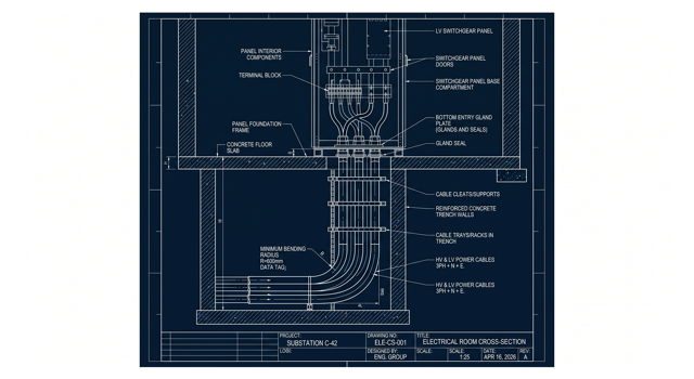
Standard floor plans are not enough for these critical zones. You must provide a highly detailed electrical room trench detail. Utilities expect to see how massive bundles of cables transition from underground trenches or raised floors up into the switchgear. Providing a detailed, scaled 2D cross-section of the substation cable entry proves that the trench is deep enough to accommodate the bending radius of the incoming utility cables and that there is sufficient physical space for jointers to terminate the cables safely.
Specifying Installation Methods (Method Statements)
A cable’s capacity changes drastically depending on how it is installed. A cable in the open air can carry more current than the exact same cable buried in hot desert sand.
Therefore, your routing drawings and schedules must clearly indicate the installation method for every major run. A robust cable installation method drawing will categorize whether cables are direct buried, installed in UPVC conduits, laid on perforated ladder trays, or enclosed in trunking. Because this physical reality dictates the thermal derating factors used in your calculations, adhering strictly to DEWA electrical installation standards and explicitly documenting your installation methods prevents the utility reviewer from guessing (and usually guessing conservatively, leading to rejections).
The Value of Advanced 3D Modeling (BIM)
While 2D drawings remain the standard requirement for many legacy utility portals, the industry is rapidly shifting toward Building Information Modeling (BIM).
Utilities are showing a growing appreciation for comprehensive Revit/BIM models. An electrical BIM submission provides an indisputable, 3D visualization of the entire network. Engaging experts in Cable Design Engineering who utilize 3D cable routing GCC software completely eliminates the risk of spatial rejections. When a utility engineer can navigate a 3D model and visually verify clearances, tray capacities, and wet-service separations, the confidence in the design skyrockets, often resulting in much faster approval turnarounds.
Frequently Asked Questions (FAQ)
1. Can I submit a generic cable schedule if the loads aren’t fully finalized?
No. Utilities like DEWA and SEC require finalized, firm data. Submitting “TBC” (To Be Confirmed) or generic estimates for cable sizes or loads will result in an immediate rejection. The schedule must represent the final, calculated design intent.
2. What happens if I change a cable size on site after the drawing is approved?
Any deviation from the approved drawings must be documented in the “As-Built” drawings. If you decrease a cable size, you must secure utility approval again, as it impacts safety. If you upsize for better efficiency, the As-Built drawings must reflect this before the final energization inspection.
3. How does DEWA check voltage drop if I don’t submit the full software model?
DEWA requires the voltage drop calculations to be tabulated clearly on the load schedules or cable schedules. They will manually spot-check your longest and heaviest runs using standard formulas (incorporating cable length, current, and impedance values from BS/IEC tables). If your tabulated result contradicts their manual check, they will request the full software calculation report.
4. Do I need to show earthing cables on the routing drawings?
Yes. The Main Earth Terminal (MET) connections, Earth Continuity Conductors (ECC) running alongside main feeders, and the routing to the physical earth pits must be clearly detailed on the routing floor plans and the corresponding single-line diagrams.
5. Why are cross-section drawings of electrical trenches mandatory?
Cross-sections prove constructability. In the GCC, high ambient temperatures mean cables in trenches must be spaced correctly to dissipate heat. A cross-section proves to the utility that the trench is wide enough to accommodate the required spacing and deep enough to allow thick cables to bend up into the panels without snapping their insulation.
Conclusion & Next Steps: Achieving First-Time Approval
In the demanding regulatory landscape of the GCC, meticulous documentation is the absolute fastest route to receiving your NOC and achieving energization. Utilities do not reject drawings to be difficult; they reject them to protect the grid and ensure public safety.
By treating the cable schedule and routing drawings not as an administrative chore, but as the definitive, perfectly coordinated blueprint of your facility, you eliminate ambiguity. When your SLD, schedule, and floor plans tell the exact same, mathematically proven story, utility engineers can approve your submissions with confidence.
Struggling with utility rejections or complex submission packages?
Do not let poor documentation delay your project handover. Our specialized engineering team can audit, restructure, and optimize your drawings for guaranteed compliance. Whether you need a dedicated DEWA electrical NOC consultant or comprehensive SEC drawing approval services, Elecwatts possesses the regulatory fluency and technical rigor to streamline your approvals.
Contact Elecwatts today to secure your first-time utility approvals and keep your project on schedule.