In the sprawling industrial mega-complexes of the Gulf Cooperation Council (GCC), from the massive petrochemical refineries of Jubail to the gigawatt-scale desalination facilities of Jebel Ali, the electrical infrastructure is the lifeblood of operation. To ensure these critical networks function flawlessly without catastrophic failure, partnering with a premier electrical engineering consultancy in Dubai is an absolute necessity from the earliest conceptual stages. The physical support system carrying this lifeblood is the cable tray network.
Cable trays are the critical arteries of industrial operations, physically supporting thousands of miles of high-voltage power lines, sensitive control wiring, and delicate instrumentation networks. Industrial cable tray design is not merely a matter of bolting metal ladders to a wall; it is a highly complex, multi-disciplinary engineering challenge.
In a large facility, poor cable routing large plants can lead to devastating consequences: cables overheating and catching fire, electromagnetic interference corrupting critical sensor data, or heavily loaded trays structurally collapsing under their own weight. Navigating the harsh GCC environment, strict international codes, and the sheer density of industrial utilities requires a rigorous, mathematically proven approach to tray sizing and layout. This guide explores the essential engineering principles necessary to design safe, compliant, and resilient cable tray networks for heavy industry.
Understanding Tray Fill Capacity Limits (NEC vs. IEC)
A common and dangerous mistake in industrial construction is treating a cable tray like a bottomless trench, stuffing it with as many cables as physically possible. To prevent overheating and mechanical damage, international electrical codes enforce strict limits on how full a tray can legally be.
The Code Mandates
Engineers must navigate the nuances between different global standards, primarily the National Electrical Code (NEC) and the International Electrotechnical Commission (IEC).
- NEC Cable Tray Standards: Under NEC Article 392, cable tray fill capacity is heavily regulated based on the type of tray (ladder, ventilated trough, solid bottom) and the voltage/size of the cables. For instance, multiconductor power cables (4/0 AWG and larger) must generally be installed in a single layer with specific spacing. The code dictates the maximum allowable cross-sectional fill area to ensure adequate heat dissipation.
- IEC Standards: IEC 60364 similarly dictates grouping and spacing factors, emphasizing that cables must not be piled indiscriminately.
Exceeding these fill capacities violates building codes, voids insurance policies, and guarantees premature insulation degradation due to trapped heat.

Thermal Derating and Heat Dissipation in the GCC
The primary reason for strict fill capacities is thermal management. A power cable generates significant heat ($I^2R$ losses) when carrying current. In a temperate climate, this heat dissipates into the surrounding air. In the GCC, the rules of thermodynamics are pushed to the limit.
The Desert Multiplier
When you place a heavily loaded power cable inside a tray in a 50°C ambient desert environment, the starting temperature is already dangerously close to the cable’s maximum operating limit (typically 90°C for XLPE).
- The Danger of Grouping: If you pile cables touching each other inside an unventilated tray, the heat cannot escape. The cables bake each other. This is why expert Cable Design Engineering is critical. Engineers must calculate and apply a severe cable grouping factor GCC penalty.
- Cable Thermal Derating: If six power cables are laid touching each other in a tray, their current-carrying capacity (ampacity) might be derated by 25% or more. To safely carry the required load, the engineer must drastically upsize the copper conductors, or redesign the tray layout to ensure a minimum of one cable diameter spacing between all circuits, allowing ambient air to flow around the jackets and carry the heat away.
Material Selection for Corrosive Environments
The structural integrity of the cable tray itself is highly dependent on the material chosen, especially in the aggressive atmospheres of the Middle East.
Battling Industrial and Coastal Corrosion
- HDG vs Stainless Steel Tray: For standard indoor or mild outdoor environments, Hot-Dip Galvanized (HDG) steel is the industry workhorse, providing excellent mechanical strength and basic rust protection. However, in highly corrosive areas, such as offshore platforms, coastal desalination plants, or facilities utilizing harsh chemicals, HDG will rapidly rust. In these zones, Marine-Grade Stainless Steel (SS316L) is often specified, though it comes with a massive cost premium.
- The FRP Alternative: Coastal GCC plants and chemical refineries are increasingly turning to FRP cable tray design (Fiberglass Reinforced Plastic). FRP, or GRP (Glass Reinforced Plastic), is completely immune to saline corrosion and chemical attack. It is non-conductive, lightweight, and UV-stabilized, making it an exceptional, long-lasting alternative to metallic trays in the harshest industrial sectors.
EMI Separation: Power, Control, and Instrumentation
An industrial plant is a cacophony of electrical noise. Massive Variable Frequency Drives (VFDs) and high-voltage transformers generate intense electromagnetic fields. If these fields interact with sensitive, low-voltage control signals, the plant’s automation system will fail.
The Rule of Physical Distance
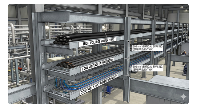
EMI cable separation (Electromagnetic Interference) is a non-negotiable layout rule. High-voltage power cables (11kV or 400V) must never be run in the same tray as low-voltage (24V DC) instrumentation cable routing or communication lines (like Fiber Optics or Ethernet).
- Multi-Tier Layouts: The standard industrial practice is to use multi-tiered tray systems. The highest voltage cables occupy the top tier, followed by low-voltage power on the middle tier, with sensitive instrumentation and control cables relegated to the bottom tier.
- Metallic Dividers: If space constraints force power and control cables into the same wide tray, a solid, grounded metallic divider barrier must be physically bolted down the center of the tray to act as a Faraday shield, blocking the magnetic interference from corrupting the sensor data.
Structural Loading and Environmental Stresses
A cable tray is a structural bridge, and it must be engineered to hold massive amounts of weight without deflecting or collapsing.
Calculating the Dead Load
Thick, multi-core, steel-wire-armored (SWA) power cables are incredibly heavy. When a 900mm wide ladder tray is fully loaded, the cable tray structural load can easily exceed hundreds of kilograms per meter. Electrical engineers must provide accurate weight-per-meter data to the structural engineering team to ensure the steel supports, cantilever arms, and ceiling anchors are robust enough to prevent catastrophic structural failure.
Wind and Seismic Factors
In exterior installations, such as massive pipe racks running kilometers across a petrochemical complex, the trays are exposed to the elements.
- The design must account for intense wind uplift and lateral loads during severe Gulf storms.
- Furthermore, in compliance with regional building codes, engineers must often integrate seismic restraint electrical tray bracing systems. These specialized shock-absorbing supports ensure that during an earthquake, the heavy, rigid tray banks sway safely with the building structure rather than snapping and severing the plant’s power supply.
Navigating Complex Industrial Layouts
Industrial facilities are a dense, three-dimensional puzzle of steel, concrete, and machinery. Routing a one-meter-wide, rigid steel cable tray through this maze requires immense foresight.
The End of 2D Drafting
Attempting to plot a massive tray network using flat, 2D AutoCAD drawings inevitably leads to disaster on the construction site. The tray will inevitably hit an HVAC duct, a chilled water pipe, or a structural steel beam that wasn’t visible on the flat electrical plan.
- BIM and Clash Detection: Today, successful electrical plant engineering uae mandates the use of Building Information Modeling (BIM). Utilizing 3D cable routing software (like Revit or Navisworks), engineers build a complete digital twin of the facility.
- Electrical BIM coordination allows the design team to run automated “clash detection” algorithms. This identifies physical intersections between the cable tray and mechanical piping in the virtual world, allowing engineers to reroute the tray seamlessly before a single piece of steel is cut on the actual construction site, saving millions in rework costs.
Earthing and Equipotential Bonding of Trays
A metallic cable tray is essentially a massive, exposed conductor running through the entire plant. If a power cable’s insulation fails and the live copper touches the steel tray, the entire tray network becomes lethally energized.
The Fault Path
To prevent electrocution and ensure the circuit breakers trip instantly during a fault, strict cable tray earthing is mandatory.
- The entire tray network must be continuously, electrically bonded to the facility’s main earth grid.
- Equipotential bonding electrical practices require the installation of flexible, tinned-copper earth braids (jumpers) bolted across every single joint, splice, and expansion gap in the tray system. This guarantees that electrical continuity is never broken, providing a zero-resistance path for short-circuit currents to safely dissipate into the ground.
Fire Proofing and Penetration Seals
Cable trays are the highways of the plant; unfortunately, if left unprotected, they also act as perfect highways for fire and toxic smoke to travel between rooms and buildings.
Preserving the Fire Compartment
When a cable tray passes through a fire-rated wall, floor slab, or enters a main substation building, it punches a hole in the fire compartment. Utility regulations and Civil Defense codes (like DCD in Dubai) strictly mandate cable tray fire stopping.
- Intumescent Solutions: The gaps between the cables and the tray, and between the tray and the wall, must be completely sealed. This is achieved using specialized fire-rated mortars, fire-stop pillows, or an intumescent cable seal.
- Under intense heat, these intumescent materials expand rapidly, crushing the melting cables and sealing the hole completely. Furthermore, in high-risk zones, entire sections of the cable tray may be coated in ablative fire-proof paint or wrapped in fire-resistant blankets to ensure circuit integrity for critical life-safety systems (like fire pumps) during a major plant fire.
Frequently Asked Questions (FAQ)
1. Can I mix power and communication cables in the same tray if I use a divider?
While a grounded metallic divider provides a degree of EMI shielding, best practice in heavy industry is to maintain complete physical separation by using different tray tiers. If mixing is unavoidable due to severe space constraints, a solid, continuous metallic divider is legally required by codes like the NEC, and shielded communication cables must be used.
2. How often do cable trays need to be supported?
Support span depends on the manufacturer’s load rating and the weight of the cables. A standard NEMA-rated ladder tray is typically supported every 1.5 meters to 3.0 meters (5 to 10 feet). Heavy-duty, long-span trays can be supported every 6 meters, but they require significantly thicker side rails to prevent deflection.
3. What is the difference between a Ladder Tray and a Solid Bottom Tray?
Ladder trays have “rungs” like a ladder, providing maximum ventilation and easy access for cables to drop down into equipment. They are the standard for heavy power cables. Solid bottom trays provide complete physical protection and EMI shielding but offer poor ventilation, requiring severe thermal derating for any power cables installed inside them.
4. Why is FRP (Fiberglass) tray not used everywhere if it doesn’t rust?
While FRP is excellent for corrosion resistance, it has drawbacks. It is generally more expensive than galvanized steel. It also requires careful support design as it can become brittle over long periods of UV exposure or under extreme heat. Most importantly, because it is non-metallic, it cannot act as an equipment grounding conductor, requiring a separate, dedicated earth cable to be run alongside it.
5. How do you handle thermal expansion of the cable tray itself?
In the GCC, a 50-meter run of steel cable tray will physically expand and contract by several centimeters between a cold winter night and a 50°C summer day. Engineers must specify “expansion splice plates” at calculated intervals. These special joints allow the tray sections to slide back and forth without buckling or ripping out the wall supports.
Conclusion & Next Steps: Organizing the Chaos
Designing the cable tray network for a large industrial plant is an exercise in organizing chaos. It is the physical manifestation of the facility’s electrical, control, and communication architecture.
A meticulously engineered layout prevents the invisible threats of thermal insulation failure and electromagnetic noise, while robust structural and material selection ensures the network survives the brutal, corrosive reality of the GCC environment. Ignoring the strict international codes regarding fill capacity, spacing, and fire-stopping transforms these critical arteries into severe operational liabilities.
Planning the infrastructure for a massive industrial facility?
Do not let poor routing or undersized trays compromise your multi-million-dirham power network. Trust a specialized industrial electrical design firm to manage the complexity. Contact our expert engineering team for flawless, 3D-coordinated industrial cable routing. As a premier GCC cable routing expert, Elecwatts ensures your infrastructure is safe, compliant, and built for ultimate reliability.Contact Elecwatts today to secure the physical foundation of your plant’s power system