

In the high-stakes realm of power transmission, substation earthing serves as the ultimate, invisible safety net protecting human life and multi-million-dollar equipment. For developers in the Middle East, establishing this critical connection to the earth presents a formidable geographical hurdle. To navigate these complexities safely, partnering with expert electrical engineering consulting in Dubai professionals from the very beginning is non-negotiable.
The challenge lies in achieving a safe, low-resistance ground path in the exceptionally dry, rocky, and sandy desert environments of the Gulf. Effective GCC substation earthing requires moving beyond standard commercial templates and executing rigorous, mathematically proven electrical grounding design studies. If the grid fails to perform during a catastrophic fault, the energy has nowhere to go but through the equipment, or worse, through the personnel standing above it. This guide explores the critical engineering methodologies, from soil testing to IEEE 80 compliance, required to anchor your high-voltage infrastructure safely into the desert earth.
The Challenge of High Soil Resistivity
The fundamental enemy of a safe grounding system in the Gulf is high soil resistivity. Unlike the moist, conductive loams found in temperate European or North American climates, the Arabian Peninsula is dominated by desiccated sand, gravel, and solid limestone bedrock.
These geological materials act more like electrical insulators than conductors, forming the core of all desert earthing challenges. When a high-voltage fault occurs (such as a lightning strike or a short circuit), a massive surge of electrical energy seeks the path of least resistance back to its source. If the earth below the substation is highly resistive, the energy struggles to dissipate, backing up and causing deadly voltage spikes above ground. To overcome this natural barrier, engineers are forced to design massive, deeply buried, and highly complex grounding grids to artificially create a safe, low-resistance dissipation pathway that the native soil simply cannot provide.
Soil Resistivity Testing: The Wenner 4-Pin Method
You cannot design a life-safety grounding grid based on geographical assumptions. Mandatory, site-specific field testing is the absolute prerequisite before any engineering design can begin.
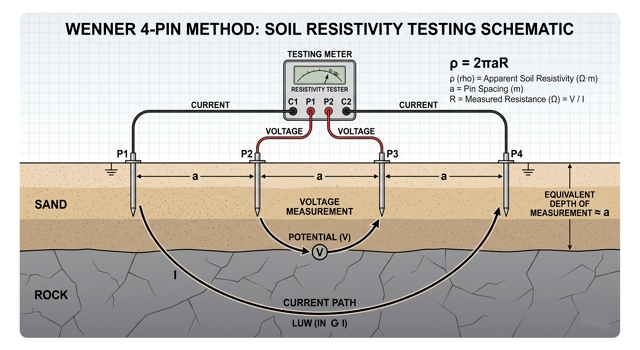
In the region, soil resistivity testing GCC protocols rely predominantly on the Wenner 4 pin method. This globally recognized technique involves driving four metal probes into the earth in a straight line at equal distances from one another. An electrical test current is injected into the ground through the outer two probes, and the resulting voltage drop is measured across the inner two probes.
By expanding the distance between the probes progressively, engineers can measure the resistivity of the soil at various depths, often revealing a highly resistive top layer of dry sand covering a more conductive, deeper layer of moist limestone or saline water table. This rich, multi-layered data is then fed into advanced software to build a precise, 3D mathematical soil model, which forms the empirical baseline for the entire earthing design.
Navigating IEEE 80 Standards
With the soil model established, the design must align with uncompromising safety regulations. The definitive global benchmark for this discipline is the IEEE 80 grounding standard (IEEE Guide for Safety in AC Substation Grounding).
Achieving substation safety compliance means strictly adhering to its complex mathematical formulas and rigorous safety thresholds. The standard’s primary objective is to calculate the maximum tolerable current that a human body (specifically modeled on a 50kg or 70kg person) can withstand passing through their heart during a fault event without experiencing fatal ventricular fibrillation. The entire grounding grid must be engineered so that any fault voltages generated above ground remain strictly below these calculated, life-or-death human tolerance limits.
Touch and Step Potential Limits
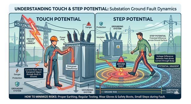
The IEEE 80 standard translates human tolerance into two critical, measurable safety metrics that define the grid’s success: touch and step potential.
- Touch Potential: This is the dangerous voltage difference between a person’s hand (assuming they are touching a grounded metallic structure, like a transformer chassis or a fence, during a fault) and their feet on the ground.
- Step Potential: This is the voltage difference between a person’s two feet (assuming a standard one-meter walking stride) as fault current dissipates radially through the earth.
As the current flows into resistive soil, it creates a steep, dangerous grounding grid voltage gradient on the surface. The physical copper grid buried below the soil must be dense enough to flatten out this voltage gradient, ensuring that the voltage differences across the surface, both touch and step potentials, never exceed the safe limits calculated in the IEEE 80 safety study.
Designing the Substation Ground Grid
The physical manifestation of the safety study is the substation ground grid design. This typically involves burying a massive copper grounding mesh horizontally across the entire footprint of the substation, usually 0.5 to 1 meter below the finished grade. To reach deeper, potentially more conductive soil layers, heavy-duty vertical copper-clad ground rods are driven deeply into the earth and exothermically welded to the horizontal mesh.
This is where expert electrical engineering consultancy services provide immense commercial and safety value. By using advanced software (like ETAP or CDEGS) to run hundreds of iterative simulations, engineers can mathematically optimize the grid spacing. They calculate exactly where the copper mesh needs to be highly dense (e.g., around operating handles and switchgear) and where it can be spaced wider. This precision engineering saves the project massive amounts of expensive raw copper while guaranteeing absolute adherence to IEEE 80 safety limits.
Soil Enhancement Materials (Bentonite & Marconite)
In many GCC desert locations, even the most optimized, densely packed copper grid cannot achieve a safe overall resistance level (typically targeting <1 ohm for large substations) due to the extreme dryness of the native soil. The engineering solution is to alter the surrounding soil chemistry using a soil enhancement material.
This involves excavating wider trenches and completely encasing the bare copper conductors and ground rods in highly conductive chemical compounds. While Bentonite clay is a traditional, low-cost option globally, it relies on retaining moisture to remain conductive, a major flaw in the 50°C GCC summer where the clay can dry out, shrink, and pull away from the copper, completely ruining the electrical connection.
Consequently, Marconite earthing GCC solutions are vastly preferred. Marconite is a specialized conductive concrete that chemically cures around the copper network. It does not require moisture to conduct, it locks the copper in place (preventing theft), and it permanently lowers the grid’s resistance regardless of the harsh, arid desert climate baking the surface above.
Perimeter Fencing and Equipment Bonding
A high-voltage substation does not exist in a vacuum; it is a high-hazard zone that must be isolated from the general public. Substation fence grounding is a highly scrutinized element of the overall design.
The metallic perimeter fence must be rigorously tied into the main ground grid (or a dedicated outer perimeter ring) to ensure that a pedestrian touching the fence from the outside during an internal plant fault is not electrocuted by transferred step or touch potentials. Furthermore, absolute electrical equipment bonding is mandatory inside the facility walls. Every single non-current-carrying metallic object, from the massive transformer chassis and high-voltage breaker frames down to the steel cable trays, building structural steel, and operating handles, must be physically bonded back to the main copper mesh using dedicated, correctly sized grounding “pigtails.”
Leading the Design and Execution
The most brilliantly modeled grounding grid is utterly worthless if it is installed incorrectly. The installation phase represents a critical point of substation civil electrical coordination. The civil contractor is eager to pour the concrete foundations and begin structural works, but the electrical team must first trench, lay, weld, and test the massive copper grid.
If the concrete is poured before the grid is fully inspected and verified, any defects are literally buried in stone and impossible to fix without catastrophic cost and delay. This is why having dedicated Project Lead Engineering & Management is essential. Rigorous grounding installation management ensures that the critical path schedule is respected, that every single exothermic weld (Cadweld) is visually inspected for integrity, and that the entire grid’s resistance is physically tested and proven to match the software model before the site is backfilled and handed over for civil works.
Frequently Asked Questions (FAQ)
1. Why can’t we just use deeper ground rods instead of a massive copper mesh?
In the GCC, driving deeper rods often hits solid limestone bedrock, which is highly resistive and impossible to penetrate easily. Furthermore, while deep rods help lower the overall resistance to remote earth, it is the dense horizontal copper mesh that is required to control the dangerous surface voltage gradients (Step and Touch Potentials) that injure personnel. Both are usually required.
2. What is an exothermic weld (Cadweld) and why is it used in earthing?
An exothermic weld is a chemical reaction that creates molten copper, permanently fusing two grounding cables (or a cable and a rod) together at a molecular level. Unlike mechanical clamps which can loosen over time or corrode in the harsh saline soils of the Gulf, an exothermic weld creates a permanent, maintenance-free connection that will never degrade or increase in electrical resistance.
3. How often should a substation’s grounding grid be tested after it is built?
While the buried grid is generally maintenance-free, international best practices and utility guidelines recommend testing the overall grid resistance and inspecting the visible above-ground bonding connections every 3 to 5 years, or immediately following any massive short-circuit fault event or major structural addition to the substation.
4. What is the target resistance for a substation grounding grid?
While it depends on the specific utility regulations (DEWA, SEC, etc.) and the size of the substation, large primary substations (132kV and above) typically target an overall grid resistance of less than 1 ohm to remote earth. Smaller distribution substations may target less than 5 ohms. However, satisfying Touch and Step potential limits is always the superseding safety priority.
5. Does adding crushed gravel (crusher run) to the substation surface improve safety?
Yes, significantly. A 100mm to 150mm layer of clean, crushed rock (like granite or basalt) is spread across the surface of the substation. Dry rock has a very high electrical resistance. This layer acts as an insulating barrier between the worker’s boots and the conductive soil below, drastically reducing the amount of fault current that can flow through the body, effectively raising the safe tolerable limits for Step and Touch potentials.
Conclusion & Next Steps: Anchoring Your Infrastructure
In the harsh, highly resistive environment of the GCC, substation grounding cannot be based on assumptions, outdated rules of thumb, or generic commercial templates. It requires precise mathematical modeling, accurate field testing, and a deep, uncompromising understanding of human physiological limits under fault conditions.
The earthing grid is the literal and figurative anchor of your electrical infrastructure; if it fails to dissipate a fault rapidly and safely, the consequences for human life and critical equipment are devastating.
Designing a new high-voltage facility or upgrading a legacy substation? Ensure your safety systems are built on an unshakable foundation. Contact our expert earthing study consultant team for comprehensive, IEEE-compliant earthing studies tailored to the specific rigors of GCC high voltage engineering standards.
Contact Elecwatts today to secure the ultimate safety net for your electrical infrastructure.