

In the execution of massive heavy industrial, oil and gas, and commercial megaprojects across the Gulf Cooperation Council (GCC), success is defined by a highly structured engineering lifecycle. Moving a project from a bare desert plot to an operational, fully energized facility requires crossing several distinct gates. To navigate these complexities, engaging a premier net zero electrical engineering consultancy is critical to establish a structured, phased execution plan.
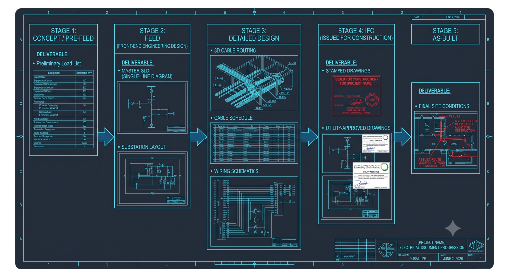
For project owners and EPC contractors alike, understanding the boundaries between different engineering project phases is the key to preventing scope creep and budget inflation. The most common and costly mistake in project management is attempting to blend or skip these phases. Specifically, misinterpreting the technical boundary of FEED vs detailed design leads directly to procurement errors, inaccurate cost estimations, and chaotic field modifications on-site. This guide deconstructs the electrical engineering roadmap, outlining the precise technical deliverables required at each stage of development.
Concept Design and Pre-FEED
Before the formal engineering design engine begins, the project exists as a series of high-level business goals and physical constraints. This is the domain of concept design engineering—often referred to as the pre-FEED phase.
In this early gate, the engineering team evaluates the macro-feasibility of the project.
- The Core Questions: For the electrical discipline, pre FEED electrical studies focus on answering the absolute, fundamental questions of power supply:
- What is the estimated total power demand of the proposed plant?
- Does the local utility grid (e.g., DEWA, SEC, or Nama Group) have the capacity to connect the facility, or will the project require on-site generation?
- Do we need to allocate land for a dedicated $33\text{ kV}$ or $132\text{ kV}$ high-voltage substation on our plot, or will an $11\text{ kV}$ feed suffice?
- The Cost Estimate: The deliverables produced in this phase are highly simplified—usually a single-page sketch and a preliminary load list. The objective is to establish a $+/- 30\%$ cost estimate, allowing the developer to decide if the project is worth pursuing further.
The Core Objective of FEED
Once the concept is deemed feasible and the project receives initial funding, it transitions into the Front-End Engineering Design (FEED) stage.
The primary objective of FEED stage engineering is to freeze the technical scope of the project, define the exact sizes of all major equipment, and eliminate technical risks. The deliverables compiled during this phase must be of sufficient detail to allow the developer to establish a highly accurate $+/- 10\%$ budget estimate. This financial baseline is the definitive package presented to boardrooms and lenders to secure the final investment decision (FID) and unlock the millions of dollars required for construction.
It is critical to note that a FEED package does not produce construction-ready drawings. A contractor cannot physically build a substation or route cables based solely on a FEED package; rather, the FEED defines the technical boundary limits and performance specifications that the subsequent construction contractor must follow.
Key Electrical FEED Deliverables
The electrical FEED package must define the baseline parameters of the facility’s power system. The core electrical FEED deliverables must include:
- Overall Main Single Line Diagram (SLD): The master roadmap of the system, showing the incoming utility connection, the main step-down transformers, medium-voltage switchgear, and the main low-voltage distribution architecture.
- Preliminary Load List: A highly calculated spreadsheet, known as the preliminary load list, that aggregates all proposed mechanical and process loads, applying specific diversity and demand factors to determine the true maximum demand of the facility.
- Major Equipment Datasheets: Technical specifications defining the rating, cooling methods, and impedance of major transformers and switchgear.
- Substation and Equipment Layouts: Scaled, 2D physical layouts of the main electrical rooms to prove that the proposed equipment can be safely accommodated, ensuring proper maintenance clearances and ventilation pathways exist on paper.
Sizing the System
Executing early power systems analysis during the FEED stage is highly critical. By running preliminary load flow, short circuit, and motor starting simulations on the digital model of the grid, engineers determine the prospective fault currents and voltage drops. This analysis locks in the mandatory short-circuit withstand capacity (kA rating) of the switchgear and the exact ratings of the transformers long before the physical construction tender is even released.

Procurement During FEED (Long-Lead Items)
In the aggressive schedules of modern construction, wait-and-see is a luxury developers cannot afford. Highly customized, heavy-duty electrical assets can command manufacturing lead times of 10 to 14 months.
This reality has birthed a highly strategic approach: sourcing long lead electrical equipment during the FEED stage.
- The Strategy: While the detailed cable routes and lighting layouts are still completely undefined, the macro-sizes of the main step-up transformers, medium-voltage switchgear, and massive variable frequency drives (VFDs) are finalized during the FEED.
- Securing the Pipeline: By executing a robust FEED procurement strategy, the developer issues early, conditional purchase orders for these heavy-value assets. This secures the manufacturer’s production slots, ensuring that the transformers and switchgear arrive on-site in perfect synchronization with the civil construction works, saving months of potential project delays.
The Transition to Detailed Design
Once the final investment decision is secured and the long-lead procurement is locked in, the project enters the detailed engineering phase. In a standard project delivery model, the FEED package is handed over to the winning Engineering, Procurement, and Construction (EPC) contractor.
The objective of the EPC electrical design phase shifts from “defining” the scope to “executing” it. Detailed engineering takes the performance-based boundaries set by the FEED and translates them into highly detailed, physical blueprints. This phase is designed to create exactly what the installers, cable-pullers, and panel-builders on the construction site need to physically build, wire, and commission the facility safely and without guessing.
Key Detailed Design Deliverables: Routing and Sizing
Detailed engineering moves from the main substation down to the individual final circuits. The deliverables in this phase are highly spatial and quantitative.
While the FEED only indicated that a cable runs from Point A to Point B, detailed design generates:
- Detailed Cable Routing Drawings: 3D and 2D layouts showing the exact physical path of every cable tray, conduit, and underground trench, fully coordinated with HVAC ducts and piping to prevent clashes.
- The Master Electrical Cable Schedule: A comprehensive electrical cable schedule database containing thousands of rows, listing the exact physical length, routing path, voltage drop, and starting current capacity of every single cable.
- Cable Tray Sizing Calculations: Proving mathematically that the physical widths of the trays comply with NEC or IEC fill-capacity limits, ensuring proper heat dissipation.
The Math of Cable Design
This is the stage where advanced Cable Design Engineering is paramount. Engineers calculate and apply precise thermal derating factors based on local GCC conditions—such as soil resistivity, extreme ambient temperatures, and cable grouping—to ensure that every single cable is safe from thermal failure.
Key Detailed Design Deliverables: Terminations and Wiring
A cable cannot simply be pulled to a panel; it must be wired. The final physical connections represent the most critical technical deliverables of the detailed phase.
Engineers must produce:
- Electrical Wiring Schematics: Meticulous, internal wiring diagrams showing the exact connection of protection relays, control switches, and current transformers inside every switchgear panel.
- Termination Schedule Drawings: A highly detailed termination schedule drawing for every cable, showing exactly which colored wire connects to which numbered terminal strip inside the junction boxes and panels.
- Block Diagrams: Visual schematics showing the overall control loops and communications between the physical field instruments, the Motor Control Centers (MCCs), and the central SCADA or DCS system.
These highly precise documents form the absolute foundation of the contractor’s site installation method statements, completely eliminating on-site guesswork by the field electricians.
The Final Output: Issued for Construction (IFC)
The ultimate milestone and climax of the detailed engineering phase is the compilation of the issued for construction electrical package.
An IFC drawing package is a legally binding, technically verified set of drawings. It represents the moment the engineering designs are formally signed off by the lead Chartered Engineers, approved by the local utility authorities (such as DEWA or SEC), and officially handed over to the site construction crews.
- Strict Change Control: Once a drawing is stamped “IFC,” it is locked. Any subsequent change—no matter how minor—requires a formal Engineering Change Proposal (ECP) or RFI (Request for Information) process. This strict change-management protocol prevents unauthorized, unsafe modifications on-site, ensuring that the physical facility built in the field remains perfectly aligned with the approved safety and compliance calculations.
Frequently Asked Questions (FAQ)
1. What is the main difference between a FEED and a Detailed Design package?
A FEED (Front-End Engineering Design) package defines the high-level technical scope, major equipment sizes, and specifications to secure project funding. A Detailed Design package takes the approved FEED and translates it into construction-ready blueprints, including 3D cable routing, wiring schematics, and termination schedules that contractors need to physically build the plant.
2. Can a contractor build a substation using only a FEED drawing package?
No. FEED drawings lack the physical, spatial, and wiring detail required for construction. For example, a FEED drawing shows where a substation will sit and its rating, but it does not show the exact cable tray routing, the terminal-to-terminal wiring of the protection relays, or the precise structural anchor bolt details required to install the switchgear safely.
3. Why are long-lead electrical items ordered during the FEED stage?
Major high-voltage assets—like 132kV transformers or custom medium-voltage switchgear—can have manufacturing lead times exceeding 12 months. Ordering these long lead electrical equipment items at the end of the FEED stage, before detailed design begins, allows the manufacturing process to run in parallel with the detailed engineering phase, saving months on the master project schedule.
4. What is a “preliminary load list” and why is it critical?
A preliminary load list is compiled during the concept and FEED stages to calculate the estimated electrical demand of the facility. It is critical because it determines the sizes of the main transformers, the required utility power allocation, and the physical footprint of the main substations. If this list is inaccurate, the entire downstream electrical design will be either significantly oversized (wasting millions in CAPEX) or dangerously undersized.
5. What does the “IFC” stamp mean on an electrical drawing?
The “IFC” (Issued for Construction) stamp means that the drawing has passed all technical reviews, is fully coordinated with other engineering disciplines (civil, mechanical, piping), has received necessary utility approvals, and is formally cleared for the site construction teams to use for purchasing materials and executing physical installation work.
Bridging the Gap
Successfully executing a multi-million-dollar energy or infrastructure project in the GCC requires absolute clarity across all electrical engineering phases. Confusing FEED deliverables with Detailed Design deliverables is a direct path to procurement errors, construction delays, and expensive variation claims on-site. By maintaining a rigorous, sequential transition—from the initial load demand and equipment sizing of the FEED to the precise cable routing, wiring, and termination schedules of the detailed phase—developers secure their investments and ensure a seamless path to utility energization.
Agility, technical precision, and localized regulatory compliance are the ultimate keys to project success.
Advancing your project to the next critical phase?
Do not risk your project timeline on uncoordinated or non-compliant design submissions. Partner with an expert team capable of managing your project’s lifecycle from concept to commissioning. As a premier FEED consultant GCC, Elecwatts provides the certified technical due diligence, advanced system simulations, and expert detailed engineering required to navigate all electrical engineering phases flawlessly, ensuring your project is delivered safely, on time, and on budget.
Contact Elecwatts today to secure the technical and operational success of your next major electrical engineering asset.