

Green hydrogen stands as the undisputed cornerstone of the GCC’s post-oil energy strategy, driving mega-projects from NEOM to Oman. However, moving from theoretical sustainability to operational reality requires more than just water and sunlight. An electrolyser plant is fundamentally a massive, highly complex electrical engineering challenge—tasked with converting gigawatts of alternating current (AC) power into chemical energy safely and efficiently. To navigate this extreme technical landscape, developers must partner with an expert electrical engineering consulting firm from the earliest conceptual stages.
Mastering green hydrogen electrical design is essential to prevent costly inefficiencies and catastrophic safety failures. It involves managing unprecedented direct current (DC) loads, mitigating severe power quality issues, and designing infrastructure that survives highly explosive environments. This guide delves deep into the electrolyser power engineering principles that dictate the success or failure of the Middle East’s most ambitious energy transition projects.
The Electrolyser Load Profile: A Massive DC Demand
At the heart of the plant are the electrolyser stacks, typically utilizing Alkaline or Proton Exchange Membrane (PEM) technologies. Their core function is electrochemistry: passing an immense electrical current through water to split it into hydrogen and oxygen.
This process creates a uniquely demanding electrolyser DC load. Unlike standard industrial plants powered by AC motors, electrolysers require pure Direct Current. The sheer scale of the power density required is staggering. A single commercial-scale stack can easily draw dozens of megawatts of continuous DC power at relatively low voltages but exceptionally high amperages (often exceeding 10,000 to 20,000 Amps).
- Technology Variances: While Alkaline systems are mature and handle steady baseloads well, PEM electrolyser power profiles are highly dynamic, capable of ramping up and down in seconds. This dynamic capability is perfect for renewable energy, but it places violent, fluctuating stress on the upstream electrical infrastructure.
Rectifier Topologies: Converting AC to DC
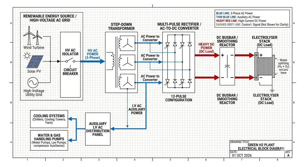
Because the utility grid and massive solar parks deliver AC power, the critical bridge to the electrolyser stack is the rectifier. This equipment executes the heavy-duty AC to DC conversion industrial process.
Electrolyser rectifier design is a balancing act of efficiency, physical footprint, and cost. Engineers primarily choose between two topologies:
- Thyristor-Based Rectifiers (SCR): The traditional workhorse. They are robust, highly reliable, and capable of handling massive currents efficiently. However, they are physically massive, generate severe harmonic distortion, and offer poor power factor at lower operating loads.
- IGBT-Based Rectifiers (Active Front End): Utilizing Insulated-Gate Bipolar Transistors, these modern rectifiers offer brilliant power quality, near-perfect power factor across all loads, and excellent dynamic response. The tradeoff is a significantly higher initial CAPEX and slightly higher internal switching losses compared to thyristors.
Managing Severe Harmonics and Power Quality
The process of converting multi-megawatt AC to DC power is a violent electrical operation. The high-power semiconductors in the rectifiers effectively “chop” the smooth AC sine wave, injecting massive amounts of “dirty power” back into the electrical grid.
This rectifier harmonic distortion is the single greatest threat to hydrogen plant power quality. It causes immense overheating in upstream transformers, degrades cables, and can destabilize the local utility grid.
- The Engineering Mandate: To mitigate this, sophisticated power system analysis and design is required long before the plant is built. Engineers must meticulously model the harmonic injection and size massive active or passive harmonic filter banks to ensure the facility meets the strict IEEE 519 standards and the uncompromising grid codes enforced by GCC utilities like DEWA or SEC.
Cooling Systems and Auxiliary Electrical Loads
While the electrolyser stack consumes the vast majority of the megawatt allowance, the support infrastructure is equally critical and electrically demanding. Splitting water and rectifying power are both exothermic processes—they generate a massive amount of waste heat.
The electrolyser cooling load accounts for a substantial percentage of the facility’s power consumption. In the 50°C summer environment of the GCC, this requires massive, heavy-duty chiller plants and heat exchangers.
- Auxiliary Demands: Beyond cooling, hydrogen plant auxiliary power must supply the high-pressure feedwater pumps, the Reverse Osmosis (RO) demineralization plants (electrolysers require ultra-pure water), and the heavy-duty compressors required to compress the highly volatile hydrogen gas for storage and transport. Sizing the secondary AC distribution network for these mechanical loads requires exact precision.
Hazardous Area Classification (ATEX) and Safety
Hydrogen is the lightest element in the universe. It leaks easily, rises rapidly, and is incredibly flammable and explosive across a massive range of concentrations in the air.
- Explosion Risk: A standard light switch or a sparking electrical motor can instantly ignite a hydrogen leak, leveling the facility.
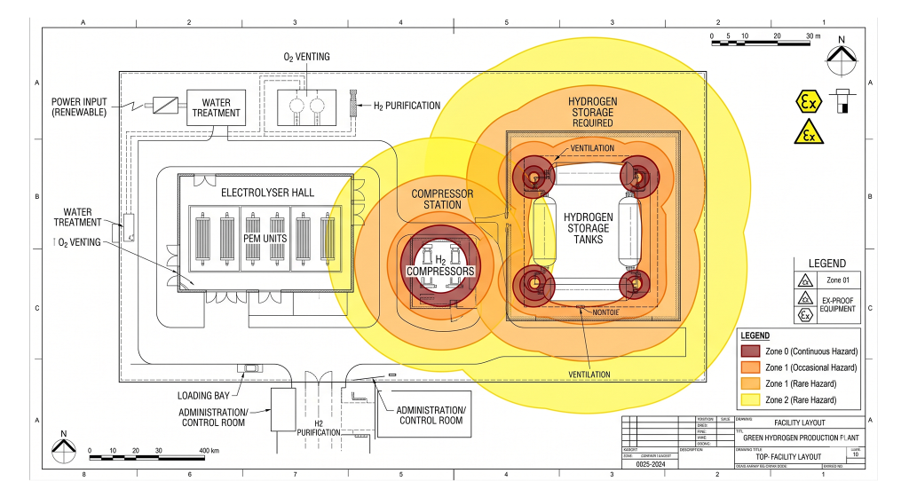
- The Compliance Standard: Consequently, robust electrical system design in these facilities requires strict ATEX Zone classifications. The entire plant must be divided into specific hazard zones (Zone 0, 1, and 2).
Achieving compliance in a hydrogen ATEX classification environment mandates uncompromising explosion proof electrical design. Every luminaire, motor, junction box, and sensor within the hazardous radius must be intrinsically safe (Ex i) or flameproof (Ex d), heavily armored to contain any internal spark and prevent it from interacting with ambient hydrogen gas.
Synchronization with Intermittent Renewables
The defining characteristic of “Green” hydrogen is that the electricity must come from renewable sources—primarily solar PV and wind. These sources are inherently intermittent; a passing cloud or a drop in wind speed instantly slashes the available power.
Achieving true renewable hydrogen synchronization means the electrolyser must act as a dynamic, flexible load.
- Dynamic Operation: The rectifiers and the plant control system must be engineered for rapid electrolyser load following. When a massive solar farm peaks at noon, the electrolysers must ramp up to 100% capacity. When clouds roll in, they must instantly throttle down to 20% to avoid draining the grid. Engineering the electrical control loops to manage these violent power swings without degrading the delicate membranes inside the electrolyser stacks is a cutting-edge challenge in modern automation.
Heavy Current Busbar Design and DC Cabling
Moving standard AC power involves relatively thick cables. Moving the low-voltage, ultra-high-amperage DC power required by an electrolyser stack requires re-imagining electrical transport altogether.
Transporting 10,000+ Amps from the rectifier room to the electrolyser stack makes standard cables obsolete. This requires extreme electrolyser cabling design.
- Massive Conductors: Engineers utilize a customized high current DC busbar network. These are enormous, solid copper or aluminum rails.
- Thermal & Magnetic Management: Pushing 10,000 Amps generates immense heat, often requiring the busbars to be internally water-cooled. Furthermore, such massive DC currents generate incredibly powerful localized magnetic fields. If the positive and negative busbars are not perfectly routed and structurally braced, the magnetic forces can physically rip the heavy metal bars right off the walls.
Substation Design for Gigawatt-Scale Plants
Green hydrogen mega-projects, such as those planned in NEOM or Duqm, are not measured in megawatts; they are measured in gigawatts.
A 2-Gigawatt electrolyser facility requires a hydrogen plant substation that rivals the size of a national grid hub.
- Transmission Level Infrastructure: This involves stepping down power from the massive 380kV or 132kV transmission networks. It requires colossal, specialized power transformers and heavy-duty Gas Insulated Switchgear (GIS).
- Resilience: The design must feature redundant gigawatt scale electrical infrastructure. Even if the primary renewable grid fails, the plant’s massive cooling systems and safety ventilation networks must be powered instantly by on-site diesel generators or utility battery backups. If an electrolyser loses power and cooling simultaneously, the thermal runaway risk is severe.
Frequently Asked Questions (FAQ)
1. Why do electrolysers require DC power instead of AC power?
Electrolysis is a chemical process that works by passing a current through water between an anode and a cathode to split the $H_2O$ molecules. This requires a constant, unidirectional flow of electrons (Direct Current). Alternating Current (AC) reverses direction 50 or 60 times a second, which would simply mix the hydrogen and oxygen back together, defeating the process entirely.
2. What is the difference between Alkaline and PEM electrolysers electrically?
Alkaline electrolysers are older, highly robust, but they prefer operating at steady, constant power loads. PEM (Proton Exchange Membrane) electrolysers are more expensive but highly agile. Electrically, PEM stacks can safely ramp their power consumption from 0% to 100% in a matter of seconds, making them far superior for pairing with unpredictable renewable energy sources like wind and solar.
3. Why are water-cooled busbars used in hydrogen plants?
An electrolyser draws massive amounts of current (often over 10,000 Amps). Pushing this much current through solid copper creates extreme resistive heat. Air cooling is often insufficient for solid bars of this size. Water-cooled busbars feature hollow channels inside the copper where chilled water flows, aggressively removing the heat and preventing the electrical connections from melting.
4. What does ATEX compliance mean for a hydrogen plant?
Hydrogen gas is extremely explosive. ATEX (Atmosphères Explosibles) is a stringent safety standard for equipment used in explosive environments. In a green hydrogen plant, ATEX compliance means that every single electrical device (lights, motors, sensors) within a designated hazard zone is specially engineered to prevent sparks or heat from igniting ambient hydrogen gas.
5. How do green hydrogen plants impact the local power grid?
Without proper engineering, they can impact it severely. The massive rectifiers used to convert AC to DC power create significant “harmonic distortion” (electrical noise) and consume vast amounts of reactive power. To protect the local grid, hydrogen plants must be engineered with massive active harmonic filters and power factor correction equipment to ensure they draw “clean” power from the utility.
Engineering the Energy Transition
The transition from a fossil-fuel economy to a green hydrogen future is not merely an environmental policy; it is a brutal, uncompromising test of heavy electrical engineering. The viability, profitability, and safety of a green hydrogen plant rest entirely on the efficiency and resilience of its electrical power conversion system.
From the 380kV incoming grid connection down to the exact routing of the water-cooled DC busbars, every component must be flawlessly designed to handle gigawatt-scale power flows, explosive ATEX atmospheres, and the volatile nature of renewable energy integration.
Are you designing a next-generation hydrogen production facility?
Do not let poorly engineered power infrastructure jeopardize your multi-billion-dollar energy asset. Partner with our expert engineering team to ensure safe, scalable, and grid-compliant infrastructure. As a premier green hydrogen consultant, Elecwatts provides the rigorous hydrogen electrical engineering GCC expertise required to power the molecule of the future safely and profitably.
Contact Elecwatts today to secure the electrical integrity of your green hydrogen mega-project.