In the sprawling power transmission networks of the Middle East, the cables themselves are rarely the source of a blackout. The vast majority of high-voltage outages occur at the precise points where the cable is cut, spliced, or connected to equipment. To safeguard this critical infrastructure, engaging a specialized electrical consultancy in Dubai from the earliest design stages is absolutely vital. The art and science of HV cable jointing GCC standards must account for an unforgiving environment.
The GCC subjects electrical infrastructure to extreme environmental stressors: blistering ambient temperatures that cause cables to expand and contract violently, airborne salinity, and 100% coastal humidity. Under these conditions, the margin for error in terminating an 11kV or 33kV line is zero. A microscopic mistake made by a technician today will inevitably manifest as a catastrophic high voltage termination failure months or years down the line, resulting in massive arc flashes, destroyed switchgear, and millions of dirhams in unplanned downtime. This guide dissects the most common failure modes in high-voltage splicing and details the uncompromising best practices required to forge unbreakable links in your power chain.
Failure Mode 1: Poor Surface Preparation and Contamination
A high-voltage XLPE (Cross-Linked Polyethylene) cable is a precision-engineered conduit. Stripping it back to create a joint exposes its vulnerable core to the elements and human error.
The most critical and delicate step in XLPE cable preparation is the removal of the outer semi-conductive screen. This black layer must be peeled or shaved back to expose the pristine white XLPE insulation beneath.
- The Microscopic Threat: If the specialized stripping tool leaves even a microscopic score mark on the insulation, or if a tiny carbon particle from the semi-conductive layer is left behind, it creates a point of intense electrical stress.
- Contamination: Similarly, if a technician touches the exposed XLPE with a sweaty, bare hand, the salts and oils from their skin will contaminate the surface. Once the joint is energized, these contaminants form a conductive path. Over time, high voltage will “track” across this invisible path, slowly carbonizing the insulation until a massive dielectric failure occurs. Flawless semi conductive screen removal and absolute cleanliness using specialized, non-residue cleaning solvents are mandatory.
Failure Mode 2: Voids, Moisture, and Partial Discharge
The inside of a high-voltage joint must be completely solid and free of any air gaps or moisture.
When a joint is poorly assembled, tiny air pockets (voids) can be trapped between the XLPE insulation and the splice body.
- The Ionization Effect: Under high electrical stress, the air inside these voids ionizes and breaks down, creating tiny, invisible electrical sparks. This phenomenon is known as partial discharge in cable joints (PD). While PD doesn’t cause an immediate short circuit, it acts like a microscopic localized fire, slowly eating away at the surrounding insulation over months or years until the wall thickness is compromised and the joint explodes.
- The Humidity Factor: The coastal GCC climate exacerbates this. If a joint is left exposed in a humid trench for even an hour before being sealed, moisture will settle on the insulation. Once sealed, this trapped moisture ingress HV cable accelerates the electrical breakdown (water treeing), guaranteeing premature failure.

Heat Shrink vs. Cold Shrink Technologies
The technology used to seal the joint or termination has evolved significantly, offering engineers distinct choices based on the operating environment.
The Heat Shrink Tradition
Historically, HV cable joint kits utilized heat shrink technology. A technician uses a propane gas torch to apply intense heat, causing the polymeric tubes to shrink down and release internal hot-melt adhesives, sealing the joint. While effective when done perfectly, it relies heavily on the technician applying even, consistent heat without scorching the materials.
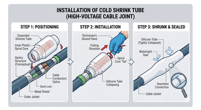
The Cold Shrink Revolution
In comparing cold shrink vs heat shrink, modern GCC installations increasingly favor cold shrink. A cold shrink tube is manufactured in an expanded state and held open by an inner plastic spiral core. The technician slides the tube into place and simply pulls out the spiral core, allowing the heavy-duty silicone rubber to dynamically shrink and compress onto the cable.
- Hazardous Area Advantage: Because cold shrink requires no open flames, it is the only viable, safe option for jointing in explosive ATEX environments like oil refineries or petrochemical plants. Furthermore, the silicone rubber expands and contracts dynamically with the cable during the extreme thermal cycling of the GCC summer, maintaining a permanent, watertight pressure seal.
The Importance of Jointer Certification and Skill
You can purchase the most expensive, highly rated termination kits in the world, but in the hands of an untrained technician, they are worthless. HV jointing is an artisan skill that requires profound understanding of electrical field theory, meticulous precision, and extreme patience.
Recognizing this, regional utility authorities treat jointing as a critical risk factor. A standard electrician is strictly prohibited from executing this work. Utilities require every technician to hold a specific DEWA approved cable jointer license or SEC equivalent. Maintaining HV cable jointer certification involves passing rigorous practical exams, proving the technician understands how to perfectly shape electrical stress-control cones and maintain absolute surgical cleanliness during the assembly process.
Termination Design for GIS vs. AIS Substations
The method used to terminate the cable changes drastically depending on the type of switchgear it is connecting to.
- Air-Insulated Switchgear (AIS): In AIS, the termination is exposed to the air inside the panel. The cable is fitted with standard AIS switchgear cable lugs, and a stress-control tube and anti-tracking “rain sheds” (if outdoor) are applied. The connection is relatively straightforward, bolted directly to the copper busbar.
- Gas-Insulated Switchgear (GIS): In modern, compact GIS substations, the high-voltage busbars are sealed inside tanks of SF6 gas. GIS cable termination is highly complex; it utilizes specialized “plug-in” or “inner cone” connectors. The cable must be perfectly prepared and pushed into a precise socket.
Because GIS panels are highly compact, there is almost no room for error in routing the thick, rigid XLPE cables. Careful Cable engineering during the design phase is paramount. The design must mathematically ensure the physical bending radius of the massive cable perfectly matches the tight spatial constraints of the termination enclosure below the GIS panel.
Earthing and Screen Bonding Practices
Every high-voltage cable features an internal copper screen or metallic sheath designed to contain the electric field and carry fault currents to the earth. If this screen is terminated incorrectly, the cable will literally cook itself.
Because AC current constantly reverses direction, it induces a voltage in the parallel metallic screen. If the screen is grounded at both ends of a long cable run, a complete circuit is formed, and massive “circulating currents” will flow through the screen, generating extreme heat that destroys the cable.
- The Engineering Solution: Flawless cable screen bonding and HV cable earthing strategies are required. For short runs, “Single-Point Bonding” is used (grounding the screen at only one end). For long transmission runs across the desert, complex “Cross-Bonding” techniques are engineered, where the screens of the three phases are systematically transposed at specialized joint boxes to mathematically cancel out the induced voltages and eliminate the circulating heat.
Mandatory Testing: VLF and PD Assessments
Once the joint is sealed and the termination is bolted in, it must be proven safe before the utility will energize the line.
Historically, engineers used high-voltage Direct Current (DC) “Hipot” tests. However, testing has evolved. Injecting massive DC voltages into modern XLPE cables causes localized trapped space charges that permanently damage the insulation.
- The Modern Standard: Today, VLF cable testing (Very Low Frequency, typically 0.1 Hz AC) is the global mandate. VLF testing safely stresses the cable’s insulation without causing permanent damage.
- The Ultimate Diagnostic: During the VLF test, specialized sensors are attached to perform partial discharge measurement. This “listens” for the microscopic sparks mentioned earlier. If the test detects PD inside a newly constructed joint, the joint is immediately rejected, cut out, and remade before it ever has a chance to fail in operation.
Site Management During Jointing
The finest jointer in the UAE cannot construct a flawless 33kV termination while standing in a dusty trench during a 45°C, high-humidity August afternoon.
The cable jointing environment dictates the success of the splice. Allowing dust or sweat to enter the jointing area is a guarantee of failure.
- The Climate-Controlled Mandate: High-voltage jointing requires the erection of sealed, air-conditioned, and dehumidified jointing tents over the trench or termination area.
- Oversight: Rigorous Electrical Construction & Commissioning Management is the only way to enforce these strict environmental controls. A dedicated commissioning manager ensures the substation construction site management protocols are respected, halting jointing operations if dust storms approach or if humidity levels inside the tent exceed the manufacturer’s strict tolerances.
Frequently Asked Questions (FAQ)
1. Can I mix power and control cables in the same tray if I use a divider?
While a grounded metallic divider provides a degree of EMI shielding, best practice in heavy industry is to maintain complete physical vertical separation by using different tray tiers. If mixing is unavoidable due to severe space constraints, a solid, continuous metallic divider is legally required, and shielded communication cables must be used.
2. What is the NEC fill limit for power cables?
For multiconductor power cables (4/0 AWG and larger), the NEC generally requires them to be installed in a single layer. The total sum of the cable diameters cannot exceed the width of the cable tray, meaning you cannot stack thick power cables on top of one another without violating code and triggering severe thermal derating penalties.
3. Why use FRP (Fiberglass) trays instead of galvanized steel?
FRP (Fiberglass Reinforced Plastic) is completely immune to rust, saltwater corrosion, and harsh chemical attacks. This makes it vastly superior to Hot-Dip Galvanized (HDG) steel for coastal desalination plants or petrochemical refineries where airborne chemicals and humidity would rapidly destroy standard metallic trays.
4. How do you fire-stop a cable tray?
When a tray penetrates a fire-rated wall, the opening must be sealed to restore the fire rating. This is done using intumescent paints, fire-stop pillows, or specialized fire-rated mortars. These materials expand massively when exposed to extreme heat, sealing off the gaps between the cables to stop flames and toxic smoke from spreading.
5. Do cable trays need to be earthed?
Yes, absolutely. A metallic cable tray is an exposed conductive part. If a live power cable gets damaged and touches the tray, the tray becomes energized. It must be bonded continuously using copper earth braids across every joint, ensuring any fault current flows safely back to the earth grid to trip the breaker instantly.
Conclusion & Next Steps: Sealing the Deal
The integrity of a multimillion-dirham power network rests entirely on the quality of its joints and terminations. In the extreme operating environment of the GCC, high voltage is unforgiving. A single microscopic void, a poorly stripped semi-conductive layer, or a drop of sweat trapped under a cold shrink tube will inevitably cascade into a catastrophic failure, halting operations and destroying equipment.
Eliminating these failures requires an uncompromising combination of elite materials, certified artisan execution, and surgical environmental control. It requires an engineering culture that refuses to cut corners in the trench.
Are you ensuring your high-voltage network is flawless?
Do not leave the weakest links in your power chain to chance. Trust our expert electrical consultancy for rigorous independent supervision, termination design, and VLF/PD testing protocols. As a premier HV cable consultant UAE, Elecwatts guarantees that your splices and terminations are engineered, executed, and tested to ensure absolute electrical network reliability for decades to come.
Contact Elecwatts today to secure the integrity of your high-voltage cable infrastructure.