The Solar Ambition vs. The Grid Reality
It is a scenario we are seeing more frequently across the GCC: A factory manager, driven by sustainability goals and the promise of reduced energy bills, commissions a large-scale rooftop solar PV system. The installation goes smoothly, and the panels look great. But the day the system is energized, the dream turns into a nightmare. A main breaker trips unexpectedly, halting production. A transformer overheats despite the load appearing normal. Sensitive control systems begin to glitch.
The thesis is simple but often overlooked: Adding a PV system to an existing plant is not just a construction project where you bolt panels to a roof; it is a major electrical intervention. You are essentially adding a volatile power plant to your facility’s internal grid. Without careful analysis, this integration can destabilize your power system and threaten your core operations.
The Unique Challenge of “Behind-the-Meter” Solar in Industry
Integrating industrial solar power is fundamentally different from building a greenfield solar farm. In a solar farm, the grid is the destination. In an existing industrial plant (“behind-the-meter”), you are modifying a live, mission-critical power system that was likely never designed to handle two power sources.
The core concern is maintaining the integrity of power quality and protection for your sensitive manufacturing equipment. When you inject solar power locally, you alter the flow of current, change voltage profiles, and introduce new frequencies. If your facility runs VFDs (Variable Frequency Drives), PLCs, or precision robotics, ignoring these changes is a recipe for expensive equipment failure.
The 5-Step Pre-Installation Study Plan (The ElecWatts Framework)
To capture the benefits of the renewable energy transition without incurring operational risks, ElecWatts utilizes a proven 5-step framework. This process de-risks the integration before a single panel is installed.
Step 1: Baseline Assessment & Data Collection
Before modeling the future, we must understand the present. We build a precise digital model of your existing electrical system. This involves verifying “As-Built” drawings against site conditions and gathering data on all major loads, existing transformers, and protective devices.
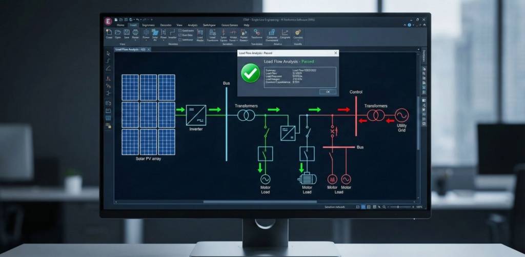
Step 2: Load Flow & Reverse Power Analysis
The most immediate question is: Will solar export overload your infrastructure? We simulate scenarios where solar generation is at its peak (noon) while plant consumption is at its minimum (e.g., weekends or maintenance shutdowns).
- The Risk: If generation exceeds load, power flows backward through the transformer. If the transformer is not rated for this bidirectional flow, it can overheat or fail.
- The Solution: We determine if the existing infrastructure can handle the export or if “Zero Export” control schemes are required to throttle the inverters.
Step 3: Short-Circuit & Contribution Study
Solar inverters are active sources of current. During a fault, they contribute to the total short-circuit current.
- The Risk: The added fault current from the solar system might push the total fault level above the interrupting rating of your existing switchgear.
- The Solution: We calculate the maximum fault contribution from the PV system and verify that your existing breakers are still safe to operate.
Step 4: Protection Coordination Re-Study
Adding a second source of power (the PV system) changes the physics of how faults are detected. This can lead to “blind spots” in your protection scheme.
- The Risk: A phenomenon known as “sympathetic tripping” can occur, where a feeder breaker trips for a fault on a different part of the system. Conversely, the solar infeed can “blind” upstream relays, causing them to trip too slowly during a fire or fault.
- The Solution: We re-evaluate the protection coordination curves and adjust relay settings to ensure the system remains selective and safe.
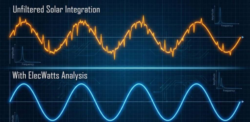
Step 5: Harmonic & Power Quality Analysis
Solar inverters convert DC to AC using high-frequency switching. This process inherently generates harmonic distortion.
- The Risk: If your plant already has high harmonic levels from VFDs, adding inverters can push Total Harmonic Distortion (THD) into dangerous territory, causing motors to overheat and electronic cards to fail.
- The Solution: We perform a Power Quality Analysis to predict the new THD levels and recommend mitigation, such as active harmonic filters, if necessary.
Navigating Utility Interconnection for On-Site Solar
Even for behind-the-meter projects, you are still connected to the utility grid. Utilities in the GCC (such as DEWA, SEC, or ADDC) have strict grid codes. They often require a simplified interconnection study to prove that your system will not destabilize their local network, particularly regarding voltage rise and frequency regulation. A professional study report is often the key document required to get your utility interconnection approved.
Conclusion: Solar Success is a Study Success
The ROI of your solar investment depends entirely on seamless integration. The financial gains from free electricity can be erased in a single day of production downtime caused by a nuisance trip or a blown transformer. Skipping the engineering studies is a gamble with your operational continuity.
By following a structured study plan, you ensure that your transition to renewable energy is boring, in the best way possible. The lights stay on, the machines keep running, and the electricity bill goes down.
Frequently Asked Questions (FAQ)
1. What happens if my factory load is lower than the solar generation on a Friday?
Power will attempt to flow backward into the utility grid. If your utility meter allows this (Net Metering), it is fine. If not, or if your transformer cannot handle it, you must install a “Zero Export” device that automatically reduces the solar inverter output to match your internal load exactly.
2. Do solar inverters really add that much fault current?
Compared to a rotating generator (like a diesel gen-set), inverters add relatively low fault current (typically 1.1 to 1.5 times their rated current). However, in older facilities where switchgear is already near its limit, even this small increase can be the “straw that breaks the camel’s back,” requiring a study to verify safety.
3. Can solar inverters damage my factory’s motors?
Indirectly, yes. If the inverters introduce high levels of harmonic distortion (noise) into the voltage supply, it can cause motors to run hotter and vibrate, shortening their lifespan. A harmonic analysis ensures this noise stays within safe IEEE 519 limits.
4. Why do I need a protection study if I’m just connecting to a spare breaker?
Because electricity flows both ways. Current from the solar panels can flow into a fault elsewhere in your plant. This changes the magnitude and direction of currents that your relays see, potentially confusing them. Adjusting the settings ensures the relays “see” the fault correctly.
5. How long does this 5-step study take?
For a typical industrial facility, the data collection and modeling process usually takes 2 to 4 weeks, depending on the quality of your existing documentation. It is a small time investment compared to the 25-year lifespan of the solar system.
Maximize your solar ROI with confidence.
ElecWatts’s 5-step study plan for existing facilities de-risks integration and ensures your plant runs smoothly, sun or no sun.
[Download our Solar Integration Checklist] or schedule a consultation to plan your project.