In electrical engineering, “ampacity” is a term that is foundational to safety and reliability. It’s more than just a number in a table; it represents the maximum continuous current a cable can carry under specific conditions without exceeding its temperature rating. Exceeding a cable’s ampacity is a direct path to premature failure. The resulting overheating degrades the cable’s insulation, creates a severe fire hazard, and compromises the integrity of the entire electrical system. A proper Cable Ampacity Calculation is therefore a non-negotiable step in responsible project design.
The Foundation: Base Ampacity from Standards
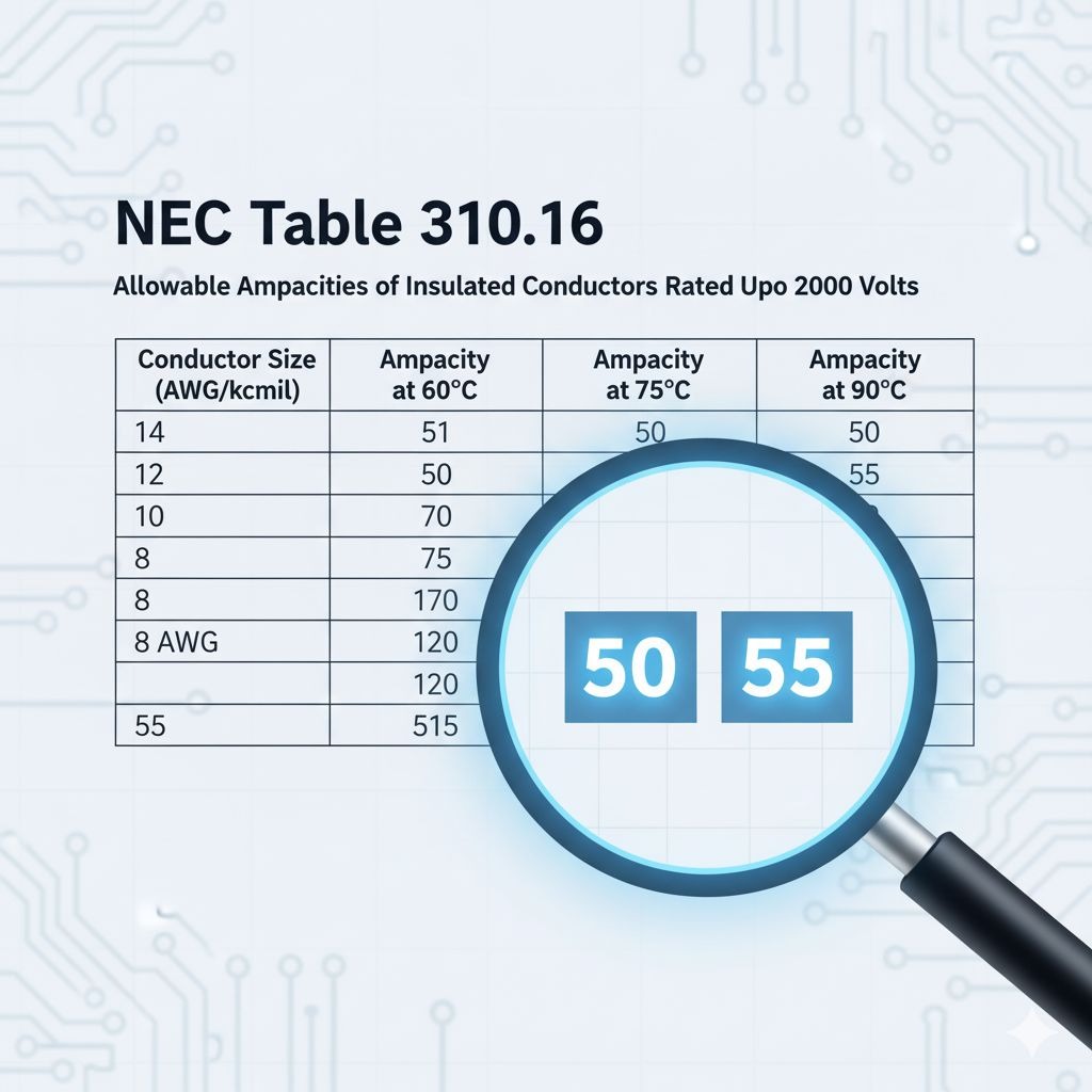
The starting point for any ampacity calculation is the set of internationally recognized standards that provide baseline values. The two most common references are the NEC (National Electrical Code) in North America and IEC 60364 for Europe and other regions. For this guide, we’ll reference a key NEC resource: NEC Table 310.16.
These tables provide the base current carrying capacity for different conductor sizes (e.g., mm², AWG), materials (copper, aluminum), and insulation temperature ratings (e.g., 60°C, 75°C, 90°C). For example, to find the base ampacity, an engineer would look up the conductor size and find the corresponding value in the column for the correct insulation temperature rating.
The Real-World Adjustments: Key Derating Factors
A cable is rarely installed in the perfect, standardized conditions assumed by the tables. To determine the real-world ampacity, we must apply “derating factors” that account for the installation environment. This process is known as cable derating.
a. Ambient Temperature
Cables dissipate heat into their surroundings. If the surrounding environment is hotter, the cable cannot dissipate heat as effectively. An ambient temperature correction factor must be applied. For example, a cable installed in the 50°C heat of a GCC summer will have a significantly lower safe ampacity than the same cable in a 20°C climate.
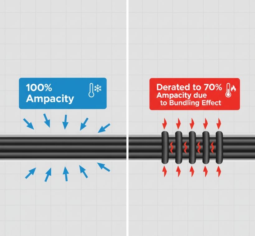
b. Cable Bundling
When multiple current-carrying cables are grouped together in a tray or conduit, their combined heat becomes trapped. This bundling effect requires a derating factor based on the number of conductors. The more cables in the bundle, the less heat each can dissipate, and the lower their individual ampacity becomes.
c. Installation Method
The way a cable is installed dramatically affects its ability to shed heat. A cable in an open-air cable tray can dissipate heat far more effectively than a cable enclosed in a conduit, which is worse still than a cable directly buried in the ground. Each method has its own derating considerations.
d. Thermal Resistivity of Soil
For direct-buried cables, the type of soil is critical. Dry, sandy soil, which is common in the GCC, has a high thermal resistivity, meaning it acts as a thermal insulator rather than a conductor. It traps heat around the cable, requiring significant derating or the selection of a much larger cable size to compensate.
Putting It All Together: A Simplified Step-by-Step Process
Here is a simplified guide to performing a basic Cable Ampacity Calculation:
- Determine the Load Current: Calculate the full load current of the equipment the cable will be supplying. This is your target.
- Select a Base Ampacity: Choose an initial cable size from a standard table (like NEC Table 310.16) that has a base ampacity higher than your load current. Note its insulation temperature rating.
- Apply All Derating Factors: Multiply the base ampacity by the applicable correction factors for ambient temperature, cable bundling, and installation method.
- Corrected Ampacity = Base Ampacity × Temperature Factor × Bundling Factor × …
- Verify the Result: The final corrected ampacity must be greater than your load current from Step 1. If it is not, you must select a larger cable size and repeat the calculation.
Example: A load requires 80A. A cable with a base ampacity of 100A is selected. It’s installed in a high-temperature environment (correction factor of 0.85) and bundled with other cables (derating factor of 0.8).
Corrected Ampacity = 100A × 0.85 × 0.8 = 68A
Since 68A is less than the 80A load, the selected cable is too small and unsafe. A larger cable must be chosen.
Conclusion: Beyond Ampacity – The Holistic View
Calculating ampacity is a critical part of cable sizing, but it is not the only factor. A holistic design must also consider:
- Voltage Drop: A cable that is correctly sized for ampacity might still be too small for a long run, causing an unacceptable voltage drop that can damage equipment.
- Short Circuit Rating: The cable must be able to withstand the immense thermal and magnetic forces of a potential short circuit.
- Overload Protection: The final cable selection must be properly coordinated with the upstream circuit breaker or fuse.
These complexities underscore the importance of professional engineering judgment. Relying on tables alone without considering derating and other factors is a recipe for undersized, unsafe installations.
Frequently Asked Questions (FAQ)
1. What is the most common mistake made in cable ampacity calculation?
The most common mistake is using the base ampacity directly from a standard table without applying the necessary derating factors for the specific installation conditions, especially ambient temperature and cable bundling.
2. Can I skip derating if my load is much lower than the cable’s base ampacity?
It is never safe to skip derating. A combination of factors (e.g., high GCC ambient temperatures and tight bundling) can reduce a cable’s true capacity by 50% or more. Always perform the calculation to ensure safety.
3. How does voltage drop relate to ampacity?
Ampacity ensures the cable doesn’t overheat (a safety calculation). Voltage drop ensures enough power reaches the equipment to operate correctly (a performance calculation). For long cable runs, you often need to select a larger cable to solve a voltage drop issue, even if a smaller cable would have been sufficient for ampacity.
4. Why is soil thermal resistivity so important for buried cables?
Buried cables rely on the surrounding soil to dissipate heat. If the soil is a poor thermal conductor (like dry sand), heat builds up around the cable, effectively “cooking” it and drastically reducing its ampacity.
5. Do I need to derate for both power and control cables in the same tray?
Typically, derating factors for bundling apply to current-carrying conductors. Low-energy control and instrumentation cables do not contribute significantly to the overall heat and are often not included in the conductor count for derating, but they can be affected by the heat from adjacent power cables.
Call to Action
Avoid costly and dangerous undersizing. Consult ElecWatts’ cable design experts to ensure optimal cable performance and safety for your project