In the world of electrical engineering, a common and costly mistake is selecting a cable based solely on its thermal capacity, or ampacity. An engineer might select a cable that can safely carry 100 amps without overheating, but if that cable needs to run 500 meters across a large industrial facility or solar farm, the voltage arriving at the other end might be insufficient to run the equipment. This phenomenon is known as voltage drop, and it is the “silent killer” of power quality issues. While ampacity ensures the cable doesn’t burn, a proper power system analysis and design ensures the connected load actually works through rigorous voltage drop calculation.
When Ampacity Isn’t Enough
The scenario is all too common: a project manager orders cable based on the “Max Current” column of a datasheet. The cable is installed, energized, and safely carries the current. However, when the motor at the end of the line attempts to start, it stalls or overheats. Or, sensitive LED lighting flickers uncontrollably.
The Problem: Voltage drop is the reduction in electrical potential along the path of a current flowing in an electrical circuit. Every conductor has internal resistance and impedance ( ZZZ). As current flows through this passive impedance, voltage is “lost” or dissipated as heat before it reaches the load.
The Risk: Operating equipment below its rated terminal voltage causes a host of problems. Resistive loads (like heaters) produce less output. Inductive loads (like motors) must draw more current to maintain power, leading to winding overheating and premature failure. Sensitive electronics may simply shut down or behave erratically.
The Standards: How Much Drop is Too Much?
While some voltage drop is inevitable, regulatory bodies set strict limits to ensure system reliability.
Regulatory Limits: The National Electrical Code (NEC 210.19 Informational Note No. 4) recommends that the maximum voltage drop on a branch circuit should not exceed 3%, and the total voltage drop for the combination of feeders and branch circuits should not exceed 5%. Adhering to these limits is standard practice for professional cable sizing for distance.
Impact on Efficiency: Voltage drop represents resistive loss—energy that is paid for but never utilized by the load. It is dissipated as waste heat (I2RI^2RI2R losses). Over the 20 or 30-year lifespan of a facility, minimizing voltage drop through proper design can result in significant operational cost savings and improved energy efficiency.

The Mathematics: Understanding the Calculation
To prevent these issues, engineers must look beyond the basic lookup tables and perform a calculation.
The Formula:
For a simple DC circuit, the formula is Ohm’s Law:
Vdrop=I×RV_{drop} = I \times RVdrop=I×R
.
However, in AC systems (which dominate GCC infrastructure), we must account for reactance (
XXX
) caused by the magnetic fields generated by the current. The voltage drop formula becomes dependent on Impedance (
ZZZ
):
Vdrop=I×ZV_{drop} = I \times ZVdrop=I×Z
Where Impedance (
ZZZ
) is a vector combination of Resistance (
RRR
) and Reactance (
XXX
).
Key Variables:
- Length: This is the critical multiplier. Voltage drop is directly proportional to cable length. Long runs, common in GCC oil fields and solar parks, require rigorous calculation.
- Load Current: Higher current results in a higher drop.
- Power Factor: In AC circuits, a lagging power factor increases the influence of the cable’s inductive reactance, exacerbating the voltage drop.
Solving the Problem: Strategies to Mitigate Voltage Drop
If a Voltage Drop Calculation reveals that your selected cable exceeds the 3% or 5% limit, there are three primary engineering strategies to mitigate the issue.
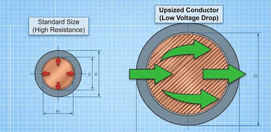
a. Upsizing the Conductor
This is the most common solution. By increasing the cross-sectional area of the conductor (e.g., moving from 50mm² to 70mm²), you reduce the resistance per meter. While this increases material cost, conductor upsizing is often the only way to maintain terminal voltage within acceptable limits over long distances.
b. Parallel Cables
For high-current applications, running multiple smaller cables in parallel (e.g., two 150mm² cables instead of one 300mm²) can sometimes reduce total impedance and reactance more effectively than a single large conductor, due to the “skin effect” and better heat dissipation.
c. Increasing System Voltage
This is the principle behind high-voltage transmission lines. By stepping up the voltage (e.g., from 400V to 11kV) for the long-distance transmission and stepping it down near the load, you significantly reduce the current required to deliver the same power. Since voltage drop is proportional to current (
III
), reducing
III
drastically reduces the drop.
Conclusion: Balancing Cost vs. Performance
Proper cable engineering is a balancing act. Upsizing cables to combat voltage drop increases the upfront capital expenditure (CAPEX). However, failing to do so increases operational expenditure (OPEX) through wasted energy and creates a high risk of equipment failure and downtime.
A professional cable study does not look at ampacity in isolation. It calculates ampacity, voltage drop, and short-circuit withstand capabilities simultaneously to find the optimal sweet spot between cost and performance.
Frequently Asked Questions (FAQ)
1. Does NEC 210.19 make voltage drop limits mandatory?
Technically, the voltage drop limits in NEC 210.19 are in an “Informational Note,” meaning they are a strong recommendation for efficiency and performance rather than a strict safety mandate like ampacity. However, ignoring them almost guarantees power quality issues and equipment malfunction, so professional engineers treat them as mandatory requirements.
2. How does voltage drop affect an electric motor?
It is counter-intuitive, but undervoltage can cause a motor to pull more current to maintain its power output. This excess current generates excess heat in the windings, significantly shortening the motor’s life and potentially tripping thermal overloads.
3. Why is the “voltage drop formula” different for AC and DC?
DC systems only have resistance (
RRR
). AC systems have both resistance and reactance (
XXX
)—resistance to the changing flow of current due to magnetic fields. In large cables or metallic conduits, reactance can be significant, so using the simple DC formula (
V=IRV=IRV=IR
) will yield an inaccurate result.
4. Can I just increase the breaker size to fix voltage drop?
Absolutely not. The breaker size protects the cable from overheating (ampacity). Increasing the breaker size does nothing to reduce the resistance of the cable, so the voltage drop remains exactly the same. The only solution is to reduce the impedance (upsize cable) or reduce the current.
5. What is the relationship between power factor and voltage drop?
A lower (lagging) power factor generally increases voltage drop because it increases the total current flowing through the cable for the same amount of useful power (kW). Improving the power factor can help reduce voltage drop.
Don’t let distance compromise your power quality. Let ElecWatts’ engineering team perform precise voltage drop calculations to optimize your electrical infrastructure and ensure your facility operates efficiently.